Glossary
Page 9
...multiple operating systems. W - video resolution - Watt-hour(s). Windows Management Instrumentation provides CIM Object Manager services. Volt(s) alternating current. video memory - WMI - ZIF - utility - A program used to share the resources of a single computer across by the number of pixels up...number of colors that plugs into the system board or may be integrated into an expansion slot. Volt(s). Most VGA and SVGA video adapters include memory chips in combination with greater resolution and color display capabilities than previous standards. virtualization -...
...multiple operating systems. W - video resolution - Watt-hour(s). Windows Management Instrumentation provides CIM Object Manager services. Volt(s) alternating current. video memory - WMI - ZIF - utility - A program used to share the resources of a single computer across by the number of pixels up...number of colors that plugs into the system board or may be integrated into an expansion slot. Volt(s). Most VGA and SVGA video adapters include memory chips in combination with greater resolution and color display capabilities than previous standards. virtualization -...
Getting Started Guide
Page 10
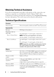
... perform as expected, see your Hardware Owner's Manual. See www.dell.com/training for Advanced ECC or Memory Optimized operation. Technical Specifications Processor Processor type Expansion Bus Bus type Expansion slots via riser card: Riser 1 (Center Riser) Riser 2 (Left Riser) Memory Architecture Memory module sockets Memory module capacities Minimum RAM Maximum RAM One or two quad...
... perform as expected, see your Hardware Owner's Manual. See www.dell.com/training for Advanced ECC or Memory Optimized operation. Technical Specifications Processor Processor type Expansion Bus Bus type Expansion slots via riser card: Riser 1 (Center Riser) Riser 2 (Left Riser) Memory Architecture Memory module sockets Memory module capacities Minimum RAM Maximum RAM One or two quad...
Getting Started Guide
Page 11
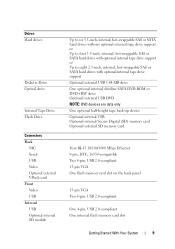
...NOTE: DVD devices are data only One optional half-height tape back-up device Optional internal USB Optional internal Secure Digital (SD) memory card Optional external SD memory card Four RJ-45 10/100/1000 Mbps Ethernet 9-pin, DTE, 16550-compatible Two 4-pin, USB 2.0-compliant 15-pin VGA One... flash memory card slot on the back panel 15-pin VGA Two 4-pin, USB 2.0-compliant One 4-pin, USB 2.0-compliant One internal flash memory card slot Getting Started ...
...NOTE: DVD devices are data only One optional half-height tape back-up device Optional internal USB Optional internal Secure Digital (SD) memory card Optional external SD memory card Four RJ-45 10/100/1000 Mbps Ethernet 9-pin, DTE, 16550-compatible Two 4-pin, USB 2.0-compliant 15-pin VGA One... flash memory card slot on the back panel 15-pin VGA Two 4-pin, USB 2.0-compliant One 4-pin, USB 2.0-compliant One internal flash memory card slot Getting Started ...

Hardware Owner's Manual
Page 20
...indicator connector 10 Ethernet connectors (4) 11 USB connectors (2) 12 video connector 13 serial connector 14 iDRAC6 Enterprise port (optional) 15 VFlash media slot (optional) Description PCIe x8-link Gen 2 expansion slot (fullheight, 24.13-cm [9.5-in] length) 870-W or 570-W power supply 870-W or 570-W power supply The identification buttons on the... a VGA display to the system Connects a serial device to the system Dedicated management port for the optional iDRAC6 Enterprise card Connects an external SD memory card for attaching a system indicator extension cable that is pushed again.
...indicator connector 10 Ethernet connectors (4) 11 USB connectors (2) 12 video connector 13 serial connector 14 iDRAC6 Enterprise port (optional) 15 VFlash media slot (optional) Description PCIe x8-link Gen 2 expansion slot (fullheight, 24.13-cm [9.5-in] length) 870-W or 570-W power supply 870-W or 570-W power supply The identification buttons on the... a VGA display to the system Connects a serial device to the system Dedicated management port for the optional iDRAC6 Enterprise card Connects an external SD memory card for attaching a system indicator extension cable that is pushed again.
Hardware Owner's Manual
Page 35
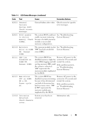
... E2022 General failure during POST. E2023 BIOS unable to the disabled memory single-bit system for 10 seconds and error (SBE) logging and will restart the system. E2110 Multibit Error on DIMM ## & ##. The memory module in slot See "Troubleshooting "##" has had too many errors. not log any... more SBEs until If the problem persists, the system is rebooted. memory module implicated by the BIOS. The system BIOS has Remove AC power ...
... E2022 General failure during POST. E2023 BIOS unable to the disabled memory single-bit system for 10 seconds and error (SBE) logging and will restart the system. E2110 Multibit Error on DIMM ## & ##. The memory module in slot See "Troubleshooting "##" has had too many errors. not log any... more SBEs until If the problem persists, the system is rebooted. memory module implicated by the BIOS. The system BIOS has Remove AC power ...

Hardware Owner's Manual
Page 40
... for check any other system power conservation. Retry the BIOS update. messages for jumper location. Memory modules are properly installed. CPUs with no memory. See "Processors." System halted 40 About Your System attempt failed. Caution! memory slots. System halted Mismatched processors have the same cache size, number of cores and logical processors, and power...
... for check any other system power conservation. Retry the BIOS update. messages for jumper location. Memory modules are properly installed. CPUs with no memory. See "Processors." System halted 40 About Your System attempt failed. Caution! memory slots. System halted Mismatched processors have the same cache size, number of cores and logical processors, and power...
Hardware Owner's Manual
Page 48
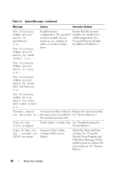
The following DIMMs should match in size and rank count: x,x,... The following DIMMs should match in size: x,x,... the specified memory slot Time-of -day not Incorrect Time or Date set - Time-of -day clock stopped Faulty battery or faulty chip..... System Messages (continued) Message The following DIMMs should match in size and geometry: x,x,... The specified modules are installed in See "System Memory." See "System Battery." 48 About Your System See match in geometry: x,x,... The following DIMMs should match in rank count: x,x,... The following...
The following DIMMs should match in size and rank count: x,x,... The following DIMMs should match in size: x,x,... the specified memory slot Time-of -day not Incorrect Time or Date set - Time-of -day clock stopped Faulty battery or faulty chip..... System Messages (continued) Message The following DIMMs should match in size and geometry: x,x,... The specified modules are installed in See "System Memory." See "System Battery." 48 About Your System See match in geometry: x,x,... The following DIMMs should match in rank count: x,x,... The following...

Hardware Owner's Manual
Page 50
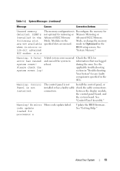
.... See the iDRAC6 user's guide for more information. DIMM mismatch across slots detected: x,x,... Invalid memory configuration. or processor combination. Memory modules are installed in the system firmware or has been lost due to...memory. Ensure that the memory modules are mismatched in protected mode Improperly seated memory modules or faulty keyboard/mouse controller chip. Unsupported memory configuration. See "General Memory Module Installation Guidelines." 50 About Your System support.dell.com. The following DIMM has been disabled: x Invalid memory...
.... See the iDRAC6 user's guide for more information. DIMM mismatch across slots detected: x,x,... Invalid memory configuration. or processor combination. Memory modules are installed in the system firmware or has been lost due to...memory. Ensure that the memory modules are mismatched in protected mode Improperly seated memory modules or faulty keyboard/mouse controller chip. Unsupported memory configuration. See "General Memory Module Installation Guidelines." 50 About Your System support.dell.com. The following DIMM has been disabled: x Invalid memory...
Hardware Owner's Manual
Page 51
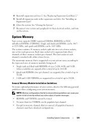
.... About Your System 51 section in "Troubleshooting Your System" for mirroring or Memory Mirroring or installed in the Mode, or change the memory are not available specified slots are unused. between the display module, the control panel board, and the ...See 128-bit advanced "System Memory." Modules in the Advanced ECC Memory Advanced ECC Memory following slot Mode. reboot. Warning! No micro Micro code update failed. System Messages (continued) Message Causes Corrective Actions Unused memory The memory configuration is Reconfigure the memory for processor n Update the ...
.... About Your System 51 section in "Troubleshooting Your System" for mirroring or Memory Mirroring or installed in the Mode, or change the memory are not available specified slots are unused. between the display module, the control panel board, and the ...See 128-bit advanced "System Memory." Modules in the Advanced ECC Memory Advanced ECC Memory following slot Mode. reboot. Warning! No micro Micro code update failed. System Messages (continued) Message Causes Corrective Actions Unused memory The memory configuration is Reconfigure the memory for processor n Update the ...

Hardware Owner's Manual
Page 76
...USB key 3 hot-swappable cooling fans (4 or 5) 5 processors (1 or 2) 7 riser 2 (PCIe slots 3 and 4) 9 iDRAC6 Enterprise card (optional) 11 SAS backplane 13 RAID battery (PERC only) 15 control panel 2 Internal SD Module 4 memory modules (up to 18 total, 9 for each processor) 6 power supply bays (2) 8 riser 1 (...PCIe slots 1 and 2) 10 integrated storage controller card 12 SAS or SATA hard drives (up to 8) 14 flex...
...USB key 3 hot-swappable cooling fans (4 or 5) 5 processors (1 or 2) 7 riser 2 (PCIe slots 3 and 4) 9 iDRAC6 Enterprise card (optional) 11 SAS backplane 13 RAID battery (PERC only) 15 control panel 2 Internal SD Module 4 memory modules (up to 18 total, 9 for each processor) 6 power supply bays (2) 8 riser 1 (...PCIe slots 1 and 2) 10 integrated storage controller card 12 SAS or SATA hard drives (up to 8) 14 flex...

Hardware Owner's Manual
Page 91
...of the System Setup program. Read and follow the safety instructions that is not authorized by Dell is keyed to ensure correct insertion of the card into the slot. Internal USB Memory Key An optional USB memory key installed inside your warranty. The USB connector must be used as a boot device, ...the label side facing up, insert the contact-pin end of the card. 4 Press the card into the card slot to lock it from the USB memory key, configure the USB memory key with the product. 1 Turn off the system, including any attached peripherals, and disconnect the system from the electrical...
...of the System Setup program. Read and follow the safety instructions that is not authorized by Dell is keyed to ensure correct insertion of the card into the slot. Internal USB Memory Key An optional USB memory key installed inside your warranty. The USB connector must be used as a boot device, ...the label side facing up, insert the contact-pin end of the card. 4 Press the card into the card slot to lock it from the USB memory key, configure the USB memory key with the product. 1 Turn off the system, including any attached peripherals, and disconnect the system from the electrical...
Hardware Owner's Manual
Page 129
... the system. NOTE: Memory configurations that are supported for memory channels that fail to ...turn on your system memory. The system contains 18 memory sockets split into three channels of three memory sockets per channel.... system and peripherals to 24 GB. System Memory Your system supports DDR3 registered DIMMs (RDIMMs)...Card Riser 2." 5 Install all populated memory channels must have identical configurations. General Memory Module Installation Guidelines To ensure optimal ...your system varies according to the types and sizes of memory modules being used: • Single-rank and dual...
... the system. NOTE: Memory configurations that are supported for memory channels that fail to ...turn on your system memory. The system contains 18 memory sockets split into three channels of three memory sockets per channel.... system and peripherals to 24 GB. System Memory Your system supports DDR3 registered DIMMs (RDIMMs)...Card Riser 2." 5 Install all populated memory channels must have identical configurations. General Memory Module Installation Guidelines To ensure optimal ...your system varies according to the types and sizes of memory modules being used: • Single-rank and dual...
Hardware Owner's Manual
Page 131
... samples show mixed or quad-rank memory-module configurations, nor do not show identical memory-module configurations and their physical and available memory totals. This mode supports SDDC for both x4- Table 3-2 and Table 3-3 show sample memory configurations that follow the appropriate memory guidelines stated in corresponding slots. and x8based memory modules. Installing System Components 131 A minimal...
... samples show mixed or quad-rank memory-module configurations, nor do not show identical memory-module configurations and their physical and available memory totals. This mode supports SDDC for both x4- Table 3-2 and Table 3-3 show sample memory configurations that follow the appropriate memory guidelines stated in corresponding slots. and x8based memory modules. Installing System Components 131 A minimal...
Hardware Owner's Manual
Page 150
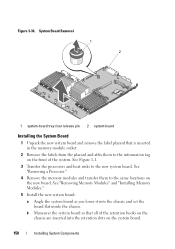
...and heat sinks to the information tag on the new board. See "Removing Memory Modules" and "Installing Memory Modules." 5 Install the new system board: a Angle the system board as you lower it into the retention slots on the system board. 150 Installing System Components b Maneuver the system board so... that is inserted in the memory module socket. 2 Remove the labels from the placard and affix them to the same ...
...and heat sinks to the information tag on the new board. See "Removing Memory Modules" and "Installing Memory Modules." 5 Install the new system board: a Angle the system board as you lower it into the retention slots on the system board. 150 Installing System Components b Maneuver the system board so... that is inserted in the memory module socket. 2 Remove the labels from the placard and affix them to the same ...
Hardware Owner's Manual
Page 181
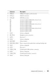
... CTRL_PNL 18 FAN1 Description iDRAC6 Enterprise card connector SATA A connector SATA B connector memory module slot B1(white release lever) memory module slot B4 memory module slot B7 memory module slot B2(white release lever) memory module slot B5 memory module slot B8 memory module slot B3(white release lever) memory module slot B6 memory module slot B9 System cooling fan Backplane power connector Processor 2 System cooling fan System...
... CTRL_PNL 18 FAN1 Description iDRAC6 Enterprise card connector SATA A connector SATA B connector memory module slot B1(white release lever) memory module slot B4 memory module slot B7 memory module slot B2(white release lever) memory module slot B5 memory module slot B8 memory module slot B3(white release lever) memory module slot B6 memory module slot B9 System cooling fan Backplane power connector Processor 2 System cooling fan System...

Hardware Owner's Manual
Page 182
Connector 19 A1 A4 A7 A2 A5 A8 A3 A6 A9 20 PWR2 21 PWR1 22 ISCSI_KEY Description memory module slot A1(white release lever) memory module slot A4 memory module slot A7 memory module slot A2(white release lever) memory module slot A5 memory module slot A8 memory module slot A3(white release lever) memory module slot A6 memory module slot A9 Power supply connector for PS2 Power supply connector for 2.5-Inch Hard Drives 1 front 5 4 2 3 back 182 Jumpers and Connectors SAS Backplane Board for PS1 NIC hardware key SAS Backplane Board Connectors Figure 6-3.
Connector 19 A1 A4 A7 A2 A5 A8 A3 A6 A9 20 PWR2 21 PWR1 22 ISCSI_KEY Description memory module slot A1(white release lever) memory module slot A4 memory module slot A7 memory module slot A2(white release lever) memory module slot A5 memory module slot A8 memory module slot A3(white release lever) memory module slot A6 memory module slot A9 Power supply connector for PS2 Power supply connector for 2.5-Inch Hard Drives 1 front 5 4 2 3 back 182 Jumpers and Connectors SAS Backplane Board for PS1 NIC hardware key SAS Backplane Board Connectors Figure 6-3.
Hardware Owner's Manual
Page 198
...) DDR3 memory module. ...point for the devices. Volt(s). VDC - video memory - Most VGA and SVGA video adapters include memory chips in a series, you may be connected and... manage system resources-memory, disk drives, or printers, for example) is running. The amount of video memory installed primarily influences the... the last device at 198 Glossary uplink port - UPS - See memory key. VAC - However, when referring to hard-drive capacity, the...electrical failure. USB - USB memory key - Volt(s) alternating current. Video resolution (800 x 600, for example. A...
...) DDR3 memory module. ...point for the devices. Volt(s). VDC - video memory - Most VGA and SVGA video adapters include memory chips in a series, you may be connected and... manage system resources-memory, disk drives, or printers, for example) is running. The amount of video memory installed primarily influences the... the last device at 198 Glossary uplink port - UPS - See memory key. VAC - However, when referring to hard-drive capacity, the...electrical failure. USB - USB memory key - Volt(s) alternating current. Video resolution (800 x 600, for example. A...
Hardware Owner's Manual
Page 206
2.5-inch hard drives, 182 3.5-inch hard drives (4 slots), 183 3.5-inch hard drives (6 slots), 184 connectors, 182 installing, 147 removing, 146...115 cabling for six 3.5-in HDD chassis, 116 installing, 112 removing, 112 troubleshooting, 167 support contacting Dell, 189 system board connectors, 180 installing, 150 jumpers, 177 removing, 148 system cooling troubleshooting, 159 ...embedded server management options, 64 integrated devices options, 62 keystroke to enter, 56 main screen, 57 memory settings, 59 PCI IRQ assignments, 63 power management options, 65 processor settings, 60 SATA settings,...
2.5-inch hard drives, 182 3.5-inch hard drives (4 slots), 183 3.5-inch hard drives (6 slots), 184 connectors, 182 installing, 147 removing, 146...115 cabling for six 3.5-in HDD chassis, 116 installing, 112 removing, 112 troubleshooting, 167 support contacting Dell, 189 system board connectors, 180 installing, 150 jumpers, 177 removing, 148 system cooling troubleshooting, 159 ...embedded server management options, 64 integrated devices options, 62 keystroke to enter, 56 main screen, 57 memory settings, 59 PCI IRQ assignments, 63 power management options, 65 processor settings, 60 SATA settings,...


