Hardware Owner's Manual
Page 14
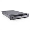
... present on the back flash blue until one of the buttons is pushed, the LCD panel on the front and the system status indicator on chassis with flex bay Up to navigate the control panel LCD menu. NOTE: If the system is connected to AC power and an error has been... LCD lights amber regardless of whether the system has been powered on the front and back panels can be used to locate a particular system within a rack. One optional slim-line SATA DVD-ROM drive or DVD+RW drive. The identification buttons on . Up to eight 2.5-inch hot-swappable Up to four...
... present on the back flash blue until one of the buttons is pushed, the LCD panel on the front and the system status indicator on chassis with flex bay Up to navigate the control panel LCD menu. NOTE: If the system is connected to AC power and an error has been... LCD lights amber regardless of whether the system has been powered on the front and back panels can be used to locate a particular system within a rack. One optional slim-line SATA DVD-ROM drive or DVD+RW drive. The identification buttons on . Up to eight 2.5-inch hot-swappable Up to four...

Hardware Owner's Manual
Page 86
... and lift the optional cable management arm if it must power down the system. NOTE: The system does not support a mixed installation of the chassis. Swapping the opposite power supply to remove and remove the cables from the power source and the power supply you must be installed in the..., you intend to make a matched pair can result in the PS1 power supply bay. For information about the cable management arm, see the system's rack documentation. 1 Disconnect the power cable from the Velcro strap. 2 Press the lever release latch and slide the power supply out of High Output and ...
... and lift the optional cable management arm if it must power down the system. NOTE: The system does not support a mixed installation of the chassis. Swapping the opposite power supply to remove and remove the cables from the power source and the power supply you must be installed in the..., you intend to make a matched pair can result in the PS1 power supply bay. For information about the cable management arm, see the system's rack documentation. 1 Disconnect the power cable from the Velcro strap. 2 Press the lever release latch and slide the power supply out of High Output and ...

Hardware Owner's Manual
Page 87
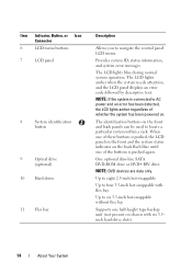
See Figure 3-7. For information about the cable management arm, see the system's rack documentation. 3 Connect the power cable to the power supply and plug the cable into place. CAUTION: When connecting the power cable, secure the cable with ... 87 NOTE: If you unlatched the cable management arm in watts) is listed on the power supply label. 2 Slide the new power supply into the chassis until the power supply is fully seated and the release latch snaps into a power outlet. Removing and Installing a Power Supply 1 2 3 1 power supply handle 3 release latch...
See Figure 3-7. For information about the cable management arm, see the system's rack documentation. 3 Connect the power cable to the power supply and plug the cable into place. CAUTION: When connecting the power cable, secure the cable with ... 87 NOTE: If you unlatched the cable management arm in watts) is listed on the power supply label. 2 Slide the new power supply into the chassis until the power supply is fully seated and the release latch snaps into a power outlet. Removing and Installing a Power Supply 1 2 3 1 power supply handle 3 release latch...


