
Glossary
Page 8
...other hubs or switches without requiring a crossover cable. U-DIMM - UPS - A battery-powered unit that automatically supplies power to your system's hardware and customize the system's ...you may use several stripes on the same set of an electrical failure. Transmission Control Protocol/Internet Protocol. termination - Uninterruptible power supply. USB memory key - VGA and...signals in memory that allows you change them again. SNMP - See also guarding, mirroring, and RAID. SVGA - system configuration information - Data stored in the cable. A BIOS-based program that...
...other hubs or switches without requiring a crossover cable. U-DIMM - UPS - A battery-powered unit that automatically supplies power to your system's hardware and customize the system's ...you may use several stripes on the same set of an electrical failure. Transmission Control Protocol/Internet Protocol. termination - Uninterruptible power supply. USB memory key - VGA and...signals in memory that allows you change them again. SNMP - See also guarding, mirroring, and RAID. SVGA - system configuration information - Data stored in the cable. A BIOS-based program that...

Hardware Owner's Manual
Page 7
... Unit 107 Installing the Tape Backup Unit 107 Removing the Tape Backup Unit 110 Integrated Storage Controller Card 111 Removing the Integrated Storage Controller Card 112 Installing the Integrated Storage Controller Card 112 RAID Battery 116 Removing a RAID Battery 116 Installing a RAID Battery 117 Cable Routing 118 Removing the Cable Retention Bracket 118 Installing the Cable Retention Bracket 119...
... Unit 107 Installing the Tape Backup Unit 107 Removing the Tape Backup Unit 110 Integrated Storage Controller Card 111 Removing the Integrated Storage Controller Card 112 Installing the Integrated Storage Controller Card 112 RAID Battery 116 Removing a RAID Battery 116 Installing a RAID Battery 117 Cable Routing 118 Removing the Cable Retention Bracket 118 Installing the Cable Retention Bracket 119...
Hardware Owner's Manual
Page 24
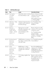
...E1000 Failsafe voltage error. If the problem persists, see "Troubleshooting Expansion Cards." 24 About Your System See "Installing a RAID Battery" and "Troubleshooting System Cooling Problems." 3.3V voltage regulator has failed. Reseat PCIe cards. system for 10 seconds and ... for critical failure events. See "Troubleshooting System Cooling Problems." E1114 Ambient Temp exceeds allowed range. E1211 RAID Controller battery failure. Reseat the RAID battery connector. Contact support. Cause Corrective Actions Check the system event log Remove AC power to the components....
...E1000 Failsafe voltage error. If the problem persists, see "Troubleshooting Expansion Cards." 24 About Your System See "Installing a RAID Battery" and "Troubleshooting System Cooling Problems." 3.3V voltage regulator has failed. Reseat PCIe cards. system for 10 seconds and ... for critical failure events. See "Troubleshooting System Cooling Problems." E1114 Ambient Temp exceeds allowed range. E1211 RAID Controller battery failure. Reseat the RAID battery connector. Contact support. Cause Corrective Actions Check the system event log Remove AC power to the components....

Hardware Owner's Manual
Page 36
... left. Remove AC power to greater than what the power supply can provide. W1628 Performance degraded. W1228 RAID Controller battery capacity < 24hr. Warns predictively that the Allow RAID battery to RAID battery has less than what the power supply can provide, but it can display sequentially on the LCD. Check... and then clear the SEL. Check the SEL for details on the events. If problem persists, replace the RAID battery. Check PSU and system configuration. The system configuration requires more power than charge to the system for details on the events.
... left. Remove AC power to greater than what the power supply can provide. W1628 Performance degraded. W1228 RAID Controller battery capacity < 24hr. Warns predictively that the Allow RAID battery to RAID battery has less than what the power supply can provide, but it can display sequentially on the LCD. Check... and then clear the SEL. Check the SEL for details on the events. If problem persists, replace the RAID battery. Check PSU and system configuration. The system configuration requires more power than charge to the system for details on the events.

Hardware Owner's Manual
Page 76
...3 hot-swappable cooling fans (4 or 5) 5 processors (1 or 2) 7 riser 2 (PCIe slots 3 and 4) 9 iDRAC6 Enterprise card (optional) 11 SAS backplane 13 RAID battery (PERC only) 15 control panel 2 Internal SD Module 4 memory modules (up to 18 total, 9 for each processor) 6 power supply bays (2) 8 riser 1 (PCIe slots 1 and 2) 10... integrated storage controller card 12 SAS or SATA hard drives (up to 8) 14 flex bay for optional tape backup unit 16...
...3 hot-swappable cooling fans (4 or 5) 5 processors (1 or 2) 7 riser 2 (PCIe slots 3 and 4) 9 iDRAC6 Enterprise card (optional) 11 SAS backplane 13 RAID battery (PERC only) 15 control panel 2 Internal SD Module 4 memory modules (up to 18 total, 9 for each processor) 6 power supply bays (2) 8 riser 1 (PCIe slots 1 and 2) 10... integrated storage controller card 12 SAS or SATA hard drives (up to 8) 14 flex bay for optional tape backup unit 16...
Hardware Owner's Manual
Page 112
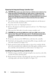
...safety instructions that is not authorized by Dell is not covered by a certified service technician. See "Removing an Expansion Card." 4 Disconnect the SAS cable(s) from expansion-card riser 1. Installing the Integrated Storage Controller Card 1 With the storage controller card-edge facing the riser, insert...and the data was not cleared at system shutdown. 5 If necessary, disconnect the RAID battery cable from the controller. 6 Bend both card-edge guides to release the controller, lift the side of the controller that is adjacent to servicing that came with the product. 1 Turn off the...
...safety instructions that is not authorized by Dell is not covered by a certified service technician. See "Removing an Expansion Card." 4 Disconnect the SAS cable(s) from expansion-card riser 1. Installing the Integrated Storage Controller Card 1 With the storage controller card-edge facing the riser, insert...and the data was not cleared at system shutdown. 5 If necessary, disconnect the RAID battery cable from the controller. 6 Bend both card-edge guides to release the controller, lift the side of the controller that is adjacent to servicing that came with the product. 1 Turn off the...

Hardware Owner's Manual
Page 113
... on the riser until the card is fully seated. See "Installing a RAID Battery." Installing a Storage Controller Card 2 1 3 4 5 8 7 6 1 dedicated storage controller card connector 3 integrated storage controller card 5 SAS_1 connector 7 SAS_0 connector 2 riser 1 4 RAID battery connector (PERC only) 6 connector locking tabs 8 card edge guides (2) 3 Slide the storage controller's card edge connector into the card slot on the cable. NOTE: Be...
... on the riser until the card is fully seated. See "Installing a RAID Battery." Installing a Storage Controller Card 2 1 3 4 5 8 7 6 1 dedicated storage controller card connector 3 integrated storage controller card 5 SAS_1 connector 7 SAS_0 connector 2 riser 1 4 RAID battery connector (PERC only) 6 connector locking tabs 8 card edge guides (2) 3 Slide the storage controller's card edge connector into the card slot on the cable. NOTE: Be...
Hardware Owner's Manual
Page 114
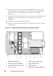
... not already done, route the interface and RAID battery cables in Hard-Drive Chassis) 1 2 3 45 6 78 1 RAID battery (PERC only) 3 SAS A connector on backplane 5 integrated storage controller card 7 SAS_1 connector 2 SAS B connector on backplane 4 cable retention bracket 6 SAS_0 connector 8 RAID battery connector (PERC only) 114 Installing System Components Storage Controller Card Cabling (2.5-in the cable path inside the...
... not already done, route the interface and RAID battery cables in Hard-Drive Chassis) 1 2 3 45 6 78 1 RAID battery (PERC only) 3 SAS A connector on backplane 5 integrated storage controller card 7 SAS_1 connector 2 SAS B connector on backplane 4 cable retention bracket 6 SAS_0 connector 8 RAID battery connector (PERC only) 114 Installing System Components Storage Controller Card Cabling (2.5-in the cable path inside the...

Hardware Owner's Manual
Page 115
Storage Controller Card Cabling (Six 3.5-in Hard-Drive Chassis) 1 2 3 45 6 78 1 RAID battery (PERC only) 3 SAS A connector on backplane 5 integrated storage controller card 7 SAS_1 connector 2 SAS B connector on backplane 4 cable retention bracket 6 SAS_0 connector 8 RAID battery connector (PERC only) Installing System Components 115 Figure 3-22.
Storage Controller Card Cabling (Six 3.5-in Hard-Drive Chassis) 1 2 3 45 6 78 1 RAID battery (PERC only) 3 SAS A connector on backplane 5 integrated storage controller card 7 SAS_1 connector 2 SAS B connector on backplane 4 cable retention bracket 6 SAS_0 connector 8 RAID battery connector (PERC only) Installing System Components 115 Figure 3-22.

Hardware Owner's Manual
Page 116
See Figure 3-24. 116 Installing System Components Removing a RAID Battery 1 Pull back gently on backplane 4 integrated storage controller card 6 RAID battery connector (PERC only) RAID Battery The information in this section applies only to systems with the optional PERC controller card. Storage Controller Card Cabling (Four 3.5-inch Hard Drive Chassis) 1 2 34 5 6 1 RAID battery (PERC only) 3 cable retention bracket 5 SAS_0 connector 2 SAS A connector...
See Figure 3-24. 116 Installing System Components Removing a RAID Battery 1 Pull back gently on backplane 4 integrated storage controller card 6 RAID battery connector (PERC only) RAID Battery The information in this section applies only to systems with the optional PERC controller card. Storage Controller Card Cabling (Four 3.5-inch Hard Drive Chassis) 1 2 34 5 6 1 RAID battery (PERC only) 3 cable retention bracket 5 SAS_0 connector 2 SAS A connector...
Hardware Owner's Manual
Page 117
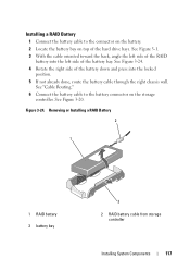
... and press into the left side of the battery bay. Removing or Installing a RAID Battery 2 1 1 RAID battery 3 battery bay 3 2 RAID battery cable from storage controller Installing System Components 117 Figure 3-24. See Figure 3-20. See "Cable Routing." 6 Connect the battery cable to the connector on the battery. 2 Locate the battery bay on the storage controller. See Figure 3-1. 3 With the cable oriented toward the...
... and press into the left side of the battery bay. Removing or Installing a RAID Battery 2 1 1 RAID battery 3 battery bay 3 2 RAID battery cable from storage controller Installing System Components 117 Figure 3-24. See Figure 3-20. See "Cable Routing." 6 Connect the battery cable to the connector on the battery. 2 Locate the battery bay on the storage controller. See Figure 3-1. 3 With the cable oriented toward the...
Hardware Owner's Manual
Page 151
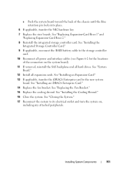
...12 Install all hard drives. See "Installing an Expansion Card." 13 If applicable, transfer the iDRAC6 Enterprise card to the storage controller card. 10 Reconnect all power and interface cables (see Figure 6-2 for the locations of the chassis until the blue retention ...-Card Riser 2." 8 Reinstall the integrated storage controller card. c Push the system board toward the back of the connectors on , including any attached peripherals. See "Installing the Integrated Storage Controller Card." 9 If applicable, reconnect the RAID battery cable to the new system board. See "Installing...
...12 Install all hard drives. See "Installing an Expansion Card." 13 If applicable, transfer the iDRAC6 Enterprise card to the storage controller card. 10 Reconnect all power and interface cables (see Figure 6-2 for the locations of the chassis until the blue retention ...-Card Riser 2." 8 Reinstall the integrated storage controller card. c Push the system board toward the back of the connectors on , including any attached peripherals. See "Installing the Integrated Storage Controller Card." 9 If applicable, reconnect the RAID battery cable to the new system board. See "Installing...

Hardware Owner's Manual
Page 168
... Integrated Storage Controller Card." 8 If you have a battery-cached PERC controller, ensure that the RAID battery is properly connected and, if applicable, the memory module on the system and attached peripherals. See "Installing the Integrated Storage Controller Card" and Figure 6-3. 10 Ensure that the controller card is ...the system from its electrical outlet, and turn on the PERC card is not covered by your warranty. See "Using Dell™ PowerEdge™ Diagnostics." 2 Turn off the system and attached peripherals, and disconnect the system from the electrical outlet. 168 ...
... Integrated Storage Controller Card." 8 If you have a battery-cached PERC controller, ensure that the RAID battery is properly connected and, if applicable, the memory module on the system and attached peripherals. See "Installing the Integrated Storage Controller Card" and Figure 6-3. 10 Ensure that the controller card is ...the system from its electrical outlet, and turn on the PERC card is not covered by your warranty. See "Using Dell™ PowerEdge™ Diagnostics." 2 Turn off the system and attached peripherals, and disconnect the system from the electrical outlet. 168 ...

Hardware Owner's Manual
Page 201
...battery (RAID) installing, 116 removing, 116 battery (system) replacing, 141 troubleshooting, 158 BIOS boot mode, 55 blank hard drive, 81 power supply, 88 boot mode, 55 C cable retention bracket installing, 119 removing, 118 cable routing, 118 cabling cable routing, 118 optical drive, 103 storage controller (2.5-in HDD chassis), 114 storage controller...20 system board, 180 USB, 12 video, 12 contacting Dell, 189 control panel assembly features, 12 LCD panel features, 15 control panel board installing, 145 removing, 144 control panel display module installing, 143 removing, 143 cooling fan ...
...battery (RAID) installing, 116 removing, 116 battery (system) replacing, 141 troubleshooting, 158 BIOS boot mode, 55 blank hard drive, 81 power supply, 88 boot mode, 55 C cable retention bracket installing, 119 removing, 118 cable routing, 118 cabling cable routing, 118 optical drive, 103 storage controller (2.5-in HDD chassis), 114 storage controller...20 system board, 180 USB, 12 video, 12 contacting Dell, 189 control panel assembly features, 12 LCD panel features, 15 control panel board installing, 145 removing, 144 control panel display module installing, 143 removing, 143 cooling fan ...
Hardware Owner's Manual
Page 203
...19 front-panel, 12 NIC, 22 power, 12, 21 information tag removing, 78 replacing, 78 installing cable retention bracket, 119 control panel board, 145 control panel display module, 143 cooling shroud, 100 expansion-card riser 1, 124 hard drive blank, 82 hard drives, 83 iDRAC6 Enterprise card...drive, 104 PCIe expansion cards, 120 power supply blank, 88 processor, 140 RAID battery, 116-117 riser 2 into expansion-card bracket, 128 SAS backplane board, 147 SD card, 90 storage controller, 112 tape backup unit, 107 VFlash SD card, 96 Integrated Dell Remote Access Controller See iDRAC6 Enterprise card.
...19 front-panel, 12 NIC, 22 power, 12, 21 information tag removing, 78 replacing, 78 installing cable retention bracket, 119 control panel board, 145 control panel display module, 143 cooling shroud, 100 expansion-card riser 1, 124 hard drive blank, 82 hard drives, 83 iDRAC6 Enterprise card...drive, 104 PCIe expansion cards, 120 power supply blank, 88 processor, 140 RAID battery, 116-117 riser 2 into expansion-card bracket, 128 SAS backplane board, 147 SD card, 90 storage controller, 112 tape backup unit, 107 VFlash SD card, 96 Integrated Dell Remote Access Controller See iDRAC6 Enterprise card.

Hardware Owner's Manual
Page 205
R RAID battery installing, 117 removing, 116 removing cable retention bracket, 118 control panel board, 144 control panel display module, 143 cooling fan, 100 cooling shroud, 99 expansion-card riser 1, 123 expansion-card riser 2, 125 fan brackets, 102 hard drive blank, 81 ... module, 90 internal USB cable, 93 memory modules, 136 optical drive, 104 PCIe expansion cards, 122 power supply, 86 power supply blank, 88 processor, 137 RAID battery, 116 riser 2 from bracket, 127 SAS backplane board, 146 SD card, 91 system board, 148 tape backup unit, 110 replacing cooling fan, 101 expansion-card...
R RAID battery installing, 117 removing, 116 removing cable retention bracket, 118 control panel board, 144 control panel display module, 143 cooling fan, 100 cooling shroud, 99 expansion-card riser 1, 123 expansion-card riser 2, 125 fan brackets, 102 hard drive blank, 81 ... module, 90 internal USB cable, 93 memory modules, 136 optical drive, 104 PCIe expansion cards, 122 power supply, 86 power supply blank, 88 processor, 137 RAID battery, 116 riser 2 from bracket, 127 SAS backplane board, 146 SD card, 91 system board, 148 tape backup unit, 110 replacing cooling fan, 101 expansion-card...


