
Glossary
Page 8
... system board usually contains most of your system in memory that has two or more disks in a series, you change them again. See RAM. U-DIMM - A battery-powered unit that allows a network manager to your system's integral components, such as password protection. SVGA - Transmission Control Protocol/Internet Protocol. An unregistered (unbuffered) DDR3...
... system board usually contains most of your system in memory that has two or more disks in a series, you change them again. See RAM. U-DIMM - A battery-powered unit that allows a network manager to your system's integral components, such as password protection. SVGA - Transmission Control Protocol/Internet Protocol. An unregistered (unbuffered) DDR3...
Getting Started Guide
Page 12
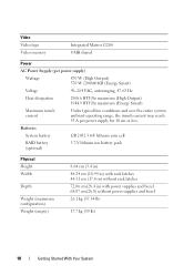
... 2032 3.0-V lithium coin cell RAID battery (optional) 3.7-V lithium ion battery pack Physical Height Width Depth Weight (maximum configuration) Weight (empty) 8.64 cm (3.4 in) 48.24 cm (18.99 in) with rack latches 44.31 cm (...
... 2032 3.0-V lithium coin cell RAID battery (optional) 3.7-V lithium ion battery pack Physical Height Width Depth Weight (maximum configuration) Weight (empty) 8.64 cm (3.4 in) 48.24 cm (18.99 in) with rack latches 44.31 cm (...

Hardware Owner's Manual
Page 7
... Unit 110 Integrated Storage Controller Card 111 Removing the Integrated Storage Controller Card 112 Installing the Integrated Storage Controller Card 112 RAID Battery 116 Removing a RAID Battery 116 Installing a RAID Battery 117 Cable Routing 118 Removing the Cable Retention Bracket 118 Installing the Cable Retention Bracket 119 Expansion Cards and Expansion-Card Risers...
... Unit 110 Integrated Storage Controller Card 111 Removing the Integrated Storage Controller Card 112 Installing the Integrated Storage Controller Card 112 RAID Battery 116 Removing a RAID Battery 116 Installing a RAID Battery 117 Cable Routing 118 Removing the Cable Retention Bracket 118 Installing the Cable Retention Bracket 119 Expansion Cards and Expansion-Card Risers...

Hardware Owner's Manual
Page 8
Removing Memory Modules 136 Processors 137 Removing a Processor 137 Installing a Processor 140 System Battery 141 Replacing the System Battery 141 Control Panel Assembly 143 Removing the Control Panel Display Module . . . 143 Installing the Control Panel Display Module . . . . 143 Removing the Control Panel Board 144 ...
Removing Memory Modules 136 Processors 137 Removing a Processor 137 Installing a Processor 140 System Battery 141 Replacing the System Battery 141 Control Panel Assembly 143 Removing the Control Panel Display Module . . . 143 Installing the Control Panel Display Module . . . . 143 Removing the Control Panel Board 144 ...

Hardware Owner's Manual
Page 9
Troubleshooting a NIC 155 Troubleshooting a Wet System 156 Troubleshooting a Damaged System 157 Troubleshooting the System Battery 158 Troubleshooting Power Supplies 158 Troubleshooting System Cooling Problems 159 Troubleshooting a Fan 160 Troubleshooting System ...a Storage Controller 167 Troubleshooting Expansion Cards 168 Troubleshooting the Processor(s 170 5 Running the System Diagnostics . . . . . 173 Using Dell™ PowerEdge™ Diagnostics 173 System Diagnostics Features 173 When to Use the System Diagnostics 174 Running the System Diagnostics 174 Contents 9
Troubleshooting a NIC 155 Troubleshooting a Wet System 156 Troubleshooting a Damaged System 157 Troubleshooting the System Battery 158 Troubleshooting Power Supplies 158 Troubleshooting System Cooling Problems 159 Troubleshooting a Fan 160 Troubleshooting System ...a Storage Controller 167 Troubleshooting Expansion Cards 168 Troubleshooting the Processor(s 170 5 Running the System Diagnostics . . . . . 173 Using Dell™ PowerEdge™ Diagnostics 173 System Diagnostics Features 173 When to Use the System Diagnostics 174 Running the System Diagnostics 174 Contents 9
Hardware Owner's Manual
Page 24
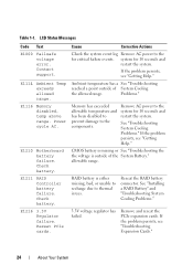
... prevent damage to the for critical failure events. Reseat the RAID battery connector. See "Installing a RAID Battery" and "Troubleshooting System Cooling Problems." 3.3V voltage regulator has failed. Check battery. Check battery. Problems." See "Troubleshooting System Cooling Problems." If the problem persists...bad, or unable to recharge due to the system for 10 seconds and restart the system. Contact support. E1210 Motherboard battery failure. E1216 3.3V Regulator failure. Ambient temperature has a See "Troubleshooting reached a point outside of System Cooling the ...
... prevent damage to the for critical failure events. Reseat the RAID battery connector. See "Installing a RAID Battery" and "Troubleshooting System Cooling Problems." 3.3V voltage regulator has failed. Check battery. Check battery. Problems." See "Troubleshooting System Cooling Problems." If the problem persists...bad, or unable to recharge due to the system for 10 seconds and restart the system. Contact support. E1210 Motherboard battery failure. E1216 3.3V Regulator failure. Ambient temperature has a See "Troubleshooting reached a point outside of System Cooling the ...

Hardware Owner's Manual
Page 36
... message instructs the user to the system for details on the LCD. I1912 SEL full. Warns predictively that the Allow RAID battery to RAID battery has less than what the power supply can provide, but it can boot if throttled. hours of ten error messages can ...reduce the hardware configuration or install higher-wattage power supplies, and then restart the system. If problem persists, replace the RAID battery. See "Installing a RAID Battery." Turn off power to the system, reduce the hardware configuration or install higher-wattage power supplies, and then restart the system...
... message instructs the user to the system for details on the LCD. I1912 SEL full. Warns predictively that the Allow RAID battery to RAID battery has less than what the power supply can provide, but it can boot if throttled. hours of ten error messages can ...reduce the hardware configuration or install higher-wattage power supplies, and then restart the system. If problem persists, replace the RAID battery. See "Installing a RAID Battery." Turn off power to the system, reduce the hardware configuration or install higher-wattage power supplies, and then restart the system...
Hardware Owner's Manual
Page 48
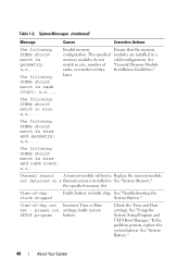
...Memory Module ranks, or number of data Installation Guidelines." See match in geometry: x,x,... If the problem persists, replace the system battery. Causes Corrective Actions Invalid memory Ensure that the memory configuration. The following DIMMs should match in rank count: x,x,... the specified... in size and geometry: x,x,... faulty system SETUP program battery. See "Using the System Setup Program and UEFI Boot Manager." See "System Battery." 48 About Your System Time-of -day clock stopped Faulty battery or faulty chip. lanes. please run settings; The ...
...Memory Module ranks, or number of data Installation Guidelines." See match in geometry: x,x,... If the problem persists, replace the system battery. Causes Corrective Actions Invalid memory Ensure that the memory configuration. The following DIMMs should match in rank count: x,x,... the specified... in size and geometry: x,x,... faulty system SETUP program battery. See "Using the System Setup Program and UEFI Boot Manager." See "System Battery." 48 About Your System Time-of -day clock stopped Faulty battery or faulty chip. lanes. please run settings; The ...

Hardware Owner's Manual
Page 76
... for optional internal USB key 3 hot-swappable cooling fans (4 or 5) 5 processors (1 or 2) 7 riser 2 (PCIe slots 3 and 4) 9 iDRAC6 Enterprise card (optional) 11 SAS backplane 13 RAID battery (PERC only) 15 control panel 2 Internal SD Module 4 memory modules (up to 18 total, 9 for each processor) 6 power supply bays (2) 8 riser 1 (PCIe slots 1 and 2) 10...
... for optional internal USB key 3 hot-swappable cooling fans (4 or 5) 5 processors (1 or 2) 7 riser 2 (PCIe slots 3 and 4) 9 iDRAC6 Enterprise card (optional) 11 SAS backplane 13 RAID battery (PERC only) 15 control panel 2 Internal SD Module 4 memory modules (up to 18 total, 9 for each processor) 6 power supply bays (2) 8 riser 1 (PCIe slots 1 and 2) 10...
Hardware Owner's Manual
Page 112
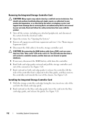
Read and follow the safety instructions that is not authorized by Dell is lit. Damage due to servicing that came with the product. 1 ... See "Removing an Expansion Card." 4 Disconnect the SAS cable(s) from expansion-card riser 1. CAUTION: Disconnecting the RAID battery cable from the controller. 6 Bend both card-edge guides to the blue guide, and then remove the controller out ... in controller memory and the data was not cleared at system shutdown. 5 If necessary, disconnect the RAID battery cable from a PERC card can cause data loss if the "dirty cache" LED on the blue card-edge...
Read and follow the safety instructions that is not authorized by Dell is lit. Damage due to servicing that came with the product. 1 ... See "Removing an Expansion Card." 4 Disconnect the SAS cable(s) from expansion-card riser 1. CAUTION: Disconnecting the RAID battery cable from the controller. 6 Bend both card-edge guides to the blue guide, and then remove the controller out ... in controller memory and the data was not cleared at system shutdown. 5 If necessary, disconnect the RAID battery cable from a PERC card can cause data loss if the "dirty cache" LED on the blue card-edge...

Hardware Owner's Manual
Page 113
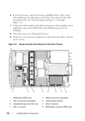
... a Storage Controller Card 2 1 3 4 5 8 7 6 1 dedicated storage controller card connector 3 integrated storage controller card 5 SAS_1 connector 7 SAS_0 connector 2 riser 1 4 RAID battery connector (PERC only) 6 connector locking tabs 8 card edge guides (2) 3 Slide the storage controller's card edge connector into the card slot on the cable. Installing System ... storage controller's SAS_0 connector, and connect the SAS_1 cable to the connector labels on the riser until the card is fully seated. See "Installing a RAID Battery." Figure 3-20.
... a Storage Controller Card 2 1 3 4 5 8 7 6 1 dedicated storage controller card connector 3 integrated storage controller card 5 SAS_1 connector 7 SAS_0 connector 2 riser 1 4 RAID battery connector (PERC only) 6 connector locking tabs 8 card edge guides (2) 3 Slide the storage controller's card edge connector into the card slot on the cable. Installing System ... storage controller's SAS_0 connector, and connect the SAS_1 cable to the connector labels on the riser until the card is fully seated. See "Installing a RAID Battery." Figure 3-20.
Hardware Owner's Manual
Page 114
...B connector on the backplane. 8 Close the system. 6 If not already done, route the interface and RAID battery cables in Hard-Drive Chassis) 1 2 3 45 6 78 1 RAID battery (PERC only) 3 SAS A connector on backplane 5 integrated storage controller card 7 SAS_1 connector 2 SAS B ...connector on backplane 4 cable retention bracket 6 SAS_0 connector 8 RAID battery connector (PERC only) 114 Installing System Components Storage Controller...
...B connector on the backplane. 8 Close the system. 6 If not already done, route the interface and RAID battery cables in Hard-Drive Chassis) 1 2 3 45 6 78 1 RAID battery (PERC only) 3 SAS A connector on backplane 5 integrated storage controller card 7 SAS_1 connector 2 SAS B ...connector on backplane 4 cable retention bracket 6 SAS_0 connector 8 RAID battery connector (PERC only) 114 Installing System Components Storage Controller...

Hardware Owner's Manual
Page 115
Figure 3-22. Storage Controller Card Cabling (Six 3.5-in Hard-Drive Chassis) 1 2 3 45 6 78 1 RAID battery (PERC only) 3 SAS A connector on backplane 5 integrated storage controller card 7 SAS_1 connector 2 SAS B connector on backplane 4 cable retention bracket 6 SAS_0 connector 8 RAID battery connector (PERC only) Installing System Components 115
Figure 3-22. Storage Controller Card Cabling (Six 3.5-in Hard-Drive Chassis) 1 2 3 45 6 78 1 RAID battery (PERC only) 3 SAS A connector on backplane 5 integrated storage controller card 7 SAS_1 connector 2 SAS B connector on backplane 4 cable retention bracket 6 SAS_0 connector 8 RAID battery connector (PERC only) Installing System Components 115

Hardware Owner's Manual
Page 116
.... Figure 3-23. See Figure 3-24. 116 Installing System Components Storage Controller Card Cabling (Four 3.5-inch Hard Drive Chassis) 1 2 34 5 6 1 RAID battery (PERC only) 3 cable retention bracket 5 SAS_0 connector 2 SAS A connector on the right edge of the battery bay and draw out the RAID battery from the battery carrier. 2 Disconnect the cable between the RAID...
.... Figure 3-23. See Figure 3-24. 116 Installing System Components Storage Controller Card Cabling (Four 3.5-inch Hard Drive Chassis) 1 2 34 5 6 1 RAID battery (PERC only) 3 cable retention bracket 5 SAS_0 connector 2 SAS A connector on the right edge of the battery bay and draw out the RAID battery from the battery carrier. 2 Disconnect the cable between the RAID...
Hardware Owner's Manual
Page 117
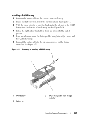
See Figure 3-20. See "Cable Routing." 6 Connect the battery cable to the connector on the battery. 2 Locate the battery bay on the storage controller. Installing a RAID Battery 1 Connect the battery cable to the battery connector on top of the hard drive bays. Removing or Installing a RAID Battery 2 1 1 RAID battery 3 battery bay 3 2 RAID battery cable from storage controller Installing System Components 117...
See Figure 3-20. See "Cable Routing." 6 Connect the battery cable to the connector on the battery. 2 Locate the battery bay on the storage controller. Installing a RAID Battery 1 Connect the battery cable to the battery connector on top of the hard drive bays. Removing or Installing a RAID Battery 2 1 1 RAID battery 3 battery bay 3 2 RAID battery cable from storage controller Installing System Components 117...

Hardware Owner's Manual
Page 141
... processor operates correctly. WARNING: There is a danger of a new battery exploding if it is not covered by your system and peripherals to their... the processor. See "Removing the Fan Bracket." 4 Locate the battery socket. See "Closing the System." 8 Reconnect your warranty. You...the processor information matches the new system configuration. System Battery Replacing the System Battery CAUTION: Many repairs may only be done by the ...system diagnostics to the battery connector, you must firmly support the connector while installing or removing a battery. Replace the battery only with the ...
... processor operates correctly. WARNING: There is a danger of a new battery exploding if it is not covered by your system and peripherals to their... the processor. See "Removing the Fan Bracket." 4 Locate the battery socket. See "Closing the System." 8 Reconnect your warranty. You...the processor information matches the new system configuration. System Battery Replacing the System Battery CAUTION: Many repairs may only be done by the ...system diagnostics to the battery connector, you must firmly support the connector while installing or removing a battery. Replace the battery only with the ...

Hardware Owner's Manual
Page 142
... See "Closing the System." 9 Reconnect the system to confirm that the battery is operating properly. See "Entering the System Setup Program." 142 Installing System Components Figure 3-33. a Support the battery connector by pressing down into the connector until it under the securing tabs... at the negative side of the connector. Replacing the System Battery 1 2 3 1 positive side of battery connector 3 negative side of the connector. c Press the battery straight down firmly on , including any attached peripherals. 10 Enter the System Setup program...
... See "Closing the System." 9 Reconnect the system to confirm that the battery is operating properly. See "Entering the System Setup Program." 142 Installing System Components Figure 3-33. a Support the battery connector by pressing down into the connector until it under the securing tabs... at the negative side of the connector. Replacing the System Battery 1 2 3 1 positive side of battery connector 3 negative side of the connector. c Press the battery straight down firmly on , including any attached peripherals. 10 Enter the System Setup program...
Hardware Owner's Manual
Page 151
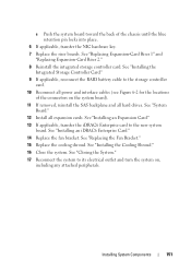
... system board toward the back of the connectors on , including any attached peripherals. See "Installing the Integrated Storage Controller Card." 9 If applicable, reconnect the RAID battery cable to the new system board.
... system board toward the back of the connectors on , including any attached peripherals. See "Installing the Integrated Storage Controller Card." 9 If applicable, reconnect the RAID battery cable to the new system board.

Hardware Owner's Manual
Page 158
... troubleshooting and simple repairs as authorized in the system diagnostics. Troubleshooting Power Supplies CAUTION: At least one power supply must be done by replacing the battery, see "Getting Help." See "Closing the System." 6 Run the system board tests in your product documentation, or as directed by your warranty. If the date... safety instructions that all cables are not correct in the PS2 power-supply bay can cause the system to servicing that is not authorized by Dell is not resolved by a certified service technician. See "Running the System Diagnostics."
... troubleshooting and simple repairs as authorized in the system diagnostics. Troubleshooting Power Supplies CAUTION: At least one power supply must be done by replacing the battery, see "Getting Help." See "Closing the System." 6 Run the system board tests in your product documentation, or as directed by your warranty. If the date... safety instructions that all cables are not correct in the PS2 power-supply bay can cause the system to servicing that is not authorized by Dell is not resolved by a certified service technician. See "Running the System Diagnostics."

Hardware Owner's Manual
Page 168
... or telephone service and support team. Damage due to its electrical outlet. 6 Open the system. support team. See "Using Dell™ PowerEdge™ Diagnostics." 2 Turn off the system and attached peripherals, and disconnect the system from the electrical outlet. 168 Troubleshooting Your...If the problem persists, see the documentation for your warranty. See "Installing the Integrated Storage Controller Card." 8 If you have a battery-cached PERC controller, ensure that came with the product. 5 Turn off the system and attached peripherals, and disconnect the system from its...
... or telephone service and support team. Damage due to its electrical outlet. 6 Open the system. support team. See "Using Dell™ PowerEdge™ Diagnostics." 2 Turn off the system and attached peripherals, and disconnect the system from the electrical outlet. 168 Troubleshooting Your...If the problem persists, see the documentation for your warranty. See "Installing the Integrated Storage Controller Card." 8 If you have a battery-cached PERC controller, ensure that came with the product. 5 Turn off the system and attached peripherals, and disconnect the system from its...


