Airborne Contaminant Level Update
Page 1
... the marks and names or their products. Dell Inc. All rights reserved. Trademarks used in trademarks and trade names other than its own. July 2010 Airborne Contaminant Level Update The following airborne contaminant level supersedes the information that is present in the Getting Started Guide of your system: Airborne Contaminant Level Class...
... the marks and names or their products. Dell Inc. All rights reserved. Trademarks used in trademarks and trade names other than its own. July 2010 Airborne Contaminant Level Update The following airborne contaminant level supersedes the information that is present in the Getting Started Guide of your system: Airborne Contaminant Level Class...
Dell PowerEdge Deployment Guide
Page 2
...other countries. For more information, contact Dell. Microsoft, Windows, and Windows Server are trademarks of Intel Corporation in any manner whatsoever without the express written permission of Dell Inc. PowerEdge Deployment Guide THIS WHITE PAPER IS FOR INFORMATIONAL PURPOSES ...ONLY, AND MAY CONTAIN TYPOGRAPHICAL ERRORS AND TECHNICAL INACCURACIES. Dell, the DELL logo, and the DELL badge, Dell OpenManage, and PowerEdge are trademarks of Dell Inc. All rights reserved...
...other countries. For more information, contact Dell. Microsoft, Windows, and Windows Server are trademarks of Intel Corporation in any manner whatsoever without the express written permission of Dell Inc. PowerEdge Deployment Guide THIS WHITE PAPER IS FOR INFORMATIONAL PURPOSES ...ONLY, AND MAY CONTAIN TYPOGRAPHICAL ERRORS AND TECHNICAL INACCURACIES. Dell, the DELL logo, and the DELL badge, Dell OpenManage, and PowerEdge are trademarks of Dell Inc. All rights reserved...
Dell PowerEdge Deployment Guide
Page 3
PowerEdge Deployment Guide Table of Contents Introduction ...2 Unified Server Configurator (USC) Deployment ...2 Dell Systems Build and Update Utility (SBUU) ...3 Dell OpenManage™ Deployment Toolkit (DTK)...3 Manual Installation of Microsoft Operating Systems 4 Microsoft WDS (Legacy Images) / RIS ...4 WinPE ...4 Microsoft Automated Deployment Service (ADS) ...4 Page 1
PowerEdge Deployment Guide Table of Contents Introduction ...2 Unified Server Configurator (USC) Deployment ...2 Dell Systems Build and Update Utility (SBUU) ...3 Dell OpenManage™ Deployment Toolkit (DTK)...3 Manual Installation of Microsoft Operating Systems 4 Microsoft WDS (Legacy Images) / RIS ...4 WinPE ...4 Microsoft Automated Deployment Service (ADS) ...4 Page 1
Dell PowerEdge Deployment Guide
Page 4
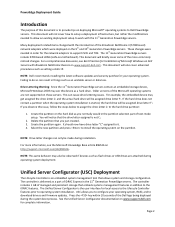
... drive will not cover how to setup a deployment infrastructure, but rather the modifications needed in the 11th Generation PowerEdge servers. Press the key within 10 seconds of the Dell logo being displayed during installation. PowerEdge Deployment Guide Introduction The purpose of this document is not C:. 2. This document will be assigned drive letter F:. These changes...
... drive will not cover how to setup a deployment infrastructure, but rather the modifications needed in the 11th Generation PowerEdge servers. Press the key within 10 seconds of the Dell logo being displayed during installation. PowerEdge Deployment Guide Introduction The purpose of this document is not C:. 2. This document will be assigned drive letter F:. These changes...
Dell PowerEdge Deployment Guide
Page 5
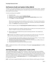
...media at this time; NOTE: The DTK does not support 64-bit WinPE at this support in the Server OS Installation. however, Dell plans to automate the operating system installation process. Using SBUU, you will reboot when the SBUU completes the initial setup for the installation.... boot to configure hardware settings such as a part of the program, www.support.dell.com for the operating system DVD. 7) The system will see all of the options in the user interface. PowerEdge Deployment Guide Dell Systems Build and Update Utility (SBUU) The SBUU is a collection of utilities that...
...media at this time; NOTE: The DTK does not support 64-bit WinPE at this support in the Server OS Installation. however, Dell plans to automate the operating system installation process. Using SBUU, you will reboot when the SBUU completes the initial setup for the installation.... boot to configure hardware settings such as a part of the program, www.support.dell.com for the operating system DVD. 7) The system will see all of the options in the user interface. PowerEdge Deployment Guide Dell Systems Build and Update Utility (SBUU) The SBUU is a collection of utilities that...
Dell PowerEdge Deployment Guide
Page 6
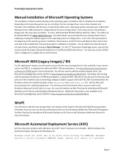
PowerEdge Deployment Guide Manual Installation of the installation due to technology changes needed to support iSCSI and TOE. Operating systems released prior to install the chipset, Broadcom NetXtreme II, and Matrox G200 video drivers. For the 11th Generation PowerEdge servers, you will also need to ...the operating system installation is in the Microsoft Knowledge Base article 254078 on http://support.microsoft.com/kb/315279. To assist, Dell developed the Dell USB Key F6 Driver Utility. Windows failed to an error while booting the RAMDISK. Please keep in your server, such ...
PowerEdge Deployment Guide Manual Installation of the installation due to technology changes needed to support iSCSI and TOE. Operating systems released prior to install the chipset, Broadcom NetXtreme II, and Matrox G200 video drivers. For the 11th Generation PowerEdge servers, you will also need to ...the operating system installation is in the Microsoft Knowledge Base article 254078 on http://support.microsoft.com/kb/315279. To assist, Dell developed the Dell USB Key F6 Driver Utility. Windows failed to an error while booting the RAMDISK. Please keep in your server, such ...
Dell PowerEdge Deployment Guide
Page 7
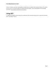
See the following Microsoft knowledge base article: http://support.microsoft.com/?id=970721 Using UEFI For additional information about using UEFI, see Deploying UEFI-Aware Operating Systems on Eleventh Generation Dell TM PowerEdgeTM Servers. Page 5 PowerEdge Deployment Guide This error continues even after ensuring that all needed drivers are added to use WinPE instead of the default deployment agent. The solution for this issue is to the PreSystem directory.
See the following Microsoft knowledge base article: http://support.microsoft.com/?id=970721 Using UEFI For additional information about using UEFI, see Deploying UEFI-Aware Operating Systems on Eleventh Generation Dell TM PowerEdgeTM Servers. Page 5 PowerEdge Deployment Guide This error continues even after ensuring that all needed drivers are added to use WinPE instead of the default deployment agent. The solution for this issue is to the PreSystem directory.
Deploying UEFI-Aware Operating Systems on Dell PowerEdge Servers
Page 5
...These definitions cover a range of the contemporary platform designs but once devices fully support GPT/UEFI, this will no longer be an issue. GUID Partition Table. GPT provides a more flexible mechanism for each device. The main characteristics of UEFI are components of the UEFI Driver Model....2‐terabyte partitions. The list of platform drivers. The drivers, analogous to both UEFI and non‐UEFI aware operating systems, the Dell BIOS supports a Boot Mode option in the future. To support booting to operating system drivers, provide support for the Operation System. The...
...These definitions cover a range of the contemporary platform designs but once devices fully support GPT/UEFI, this will no longer be an issue. GUID Partition Table. GPT provides a more flexible mechanism for each device. The main characteristics of UEFI are components of the UEFI Driver Model....2‐terabyte partitions. The list of platform drivers. The drivers, analogous to both UEFI and non‐UEFI aware operating systems, the Dell BIOS supports a Boot Mode option in the future. To support booting to operating system drivers, provide support for the Operation System. The...
Deploying UEFI-Aware Operating Systems on Dell PowerEdge Servers
Page 10
...is necessary to each partition. This allows a user to boot to access the disks using legacy abstraction supported in UEFI mode: Dell PERC 6/i Dell SAS 6/iR Future controllers will eliminate the inherent GPT partition redundancy. Page 8 Transferring Hard Disks UEFI Boot Options are copied ...UEFI mode and do not provide native access disks in the UEFI environment. Dell has addressed this problem by keeping a copy of less than 2 terabytes (TB). This scheme assigns a Globally Unique Identifier (GUID) to create the boot option on the hard disk with the operating system...
...is necessary to each partition. This allows a user to boot to access the disks using legacy abstraction supported in UEFI mode: Dell PERC 6/i Dell SAS 6/iR Future controllers will eliminate the inherent GPT partition redundancy. Page 8 Transferring Hard Disks UEFI Boot Options are copied ...UEFI mode and do not provide native access disks in the UEFI environment. Dell has addressed this problem by keeping a copy of less than 2 terabytes (TB). This scheme assigns a Globally Unique Identifier (GUID) to create the boot option on the hard disk with the operating system...
Getting Started Guide
Page 10
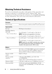
any additional cards installed in all locations. See www.dell.com/training for Advanced ECC or Memory Optimized operation. or dual-core Intel® Xeon® processors PCI Express Generation 2 One full-height, 9.5-inch length, ...-pin 1 GB and 2 GB UDIMMs, and 2 GB, 4 GB, or 8 GB RDIMMs (single, dual, or quad-rank dependent on the first two cards installed in this guide or if the system does not perform as expected, see your Hardware Owner's Manual. One low-profile, 9.5-inch length, x4 link (slot 2) Two full-height...
any additional cards installed in all locations. See www.dell.com/training for Advanced ECC or Memory Optimized operation. or dual-core Intel® Xeon® processors PCI Express Generation 2 One full-height, 9.5-inch length, ...-pin 1 GB and 2 GB UDIMMs, and 2 GB, 4 GB, or 8 GB RDIMMs (single, dual, or quad-rank dependent on the first two cards installed in this guide or if the system does not perform as expected, see your Hardware Owner's Manual. One low-profile, 9.5-inch length, x4 link (slot 2) Two full-height...
Hardware Owner's Manual
Page 26
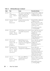
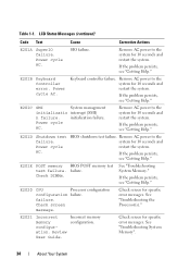
... AC. Table 1-1. LCD Status Messages (continued) Code Text Cause Corrective Actions E1313 Fan redundancy lost. system at risk of Ensure that your system's Getting Started Guide. If the problem persists, see "Getting Help." 26 About Your System installed. E1418 CPU # not detected. Specified processor is Ensure that the specified missing or...
... AC. Table 1-1. LCD Status Messages (continued) Code Text Cause Corrective Actions E1313 Fan redundancy lost. system at risk of Ensure that your system's Getting Started Guide. If the problem persists, see "Getting Help." 26 About Your System installed. E1418 CPU # not detected. Specified processor is Ensure that the specified missing or...

Hardware Owner's Manual
Page 28
... the hardware configuration or install higher-wattage power supplies, and then restart the system. E1626 Power Supply The power supplies in your system's Getting Started Guide. The system configuration requires more information and then clear the SEL. Review & clear SEL. LCD Status Messages (continued) Code Text Cause Corrective Actions E1620 Power...
... the hardware configuration or install higher-wattage power supplies, and then restart the system. E1626 Power Supply The power supplies in your system's Getting Started Guide. The system configuration requires more information and then clear the SEL. Review & clear SEL. LCD Status Messages (continued) Code Text Cause Corrective Actions E1620 Power...
Hardware Owner's Manual
Page 34
Table 1-1. Keyboard controller failure. Power cycle AC. If the problem persists, see "Getting Help." failure. Review User Guide. Power cycle AC. SIO failure. E201B Keyboard Controller error. initialization failure. E201D Shutdown test failure. Power cycle AC. failure. Remove AC power to the system ...
Table 1-1. Keyboard controller failure. Power cycle AC. If the problem persists, see "Getting Help." failure. Review User Guide. Power cycle AC. SIO failure. E201B Keyboard Controller error. initialization failure. E201D Shutdown test failure. Power cycle AC. failure. Remove AC power to the system ...

Hardware Owner's Manual
Page 50
...been lost due to system board replacement. See "General Memory Module Installation Guidelines." Unsupported memory configuration. support.dell.com. Unsupported CPU combination Unsupported CPU stepping detected Processor(s) is either corrupted in a valid configuration. Unsupported ...Message Causes Corrective Actions Unable to restore full functionality. See "Troubleshooting System Memory." See the iDRAC6 user's guide for more information. DIMM mismatch across slots detected: x,x,... See the Unified Server Configuration user documentation for instructions ...
...been lost due to system board replacement. See "General Memory Module Installation Guidelines." Unsupported memory configuration. support.dell.com. Unsupported CPU combination Unsupported CPU stepping detected Processor(s) is either corrupted in a valid configuration. Unsupported ...Message Causes Corrective Actions Unable to restore full functionality. See "Troubleshooting System Memory." See the iDRAC6 user's guide for more information. DIMM mismatch across slots detected: x,x,... See the Unified Server Configuration user documentation for instructions ...
Hardware Owner's Manual
Page 54
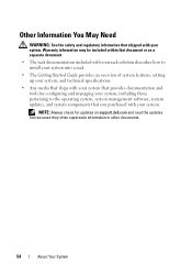
...: Always check for configuring and managing your system, including those pertaining to install your system into a rack. • The Getting Started Guide provides an overview of system features, setting up your system, and technical specifications. • Any media that ships with your system that ...provides documentation and tools for updates on support.dell.com and read the updates first because they often supersede information in other documents. 54 About Your System Other Information You May Need...
...: Always check for configuring and managing your system, including those pertaining to install your system into a rack. • The Getting Started Guide provides an overview of system features, setting up your system, and technical specifications. • Any media that ships with your system that ...provides documentation and tools for updates on support.dell.com and read the updates first because they often supersede information in other documents. 54 About Your System Other Information You May Need...

Hardware Owner's Manual
Page 93
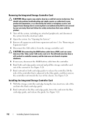
...perform troubleshooting and simple repairs as authorized in your warranty. If necessary remove any attached peripherals, and disconnect the system from the cable routing guides on the system board. 7 Replace the fan bracket. Installing the Internal USB Cable CAUTION: Many repairs may only be done by a... certified service technician. Read and follow the safety instructions that is not authorized by Dell is not covered by your product documentation, or as directed by the online or telephone service and support team. You should only ...
...perform troubleshooting and simple repairs as authorized in your warranty. If necessary remove any attached peripherals, and disconnect the system from the cable routing guides on the system board. 7 Replace the fan bracket. Installing the Internal USB Cable CAUTION: Many repairs may only be done by a... certified service technician. Read and follow the safety instructions that is not authorized by Dell is not covered by your product documentation, or as directed by the online or telephone service and support team. You should only ...
Hardware Owner's Manual
Page 112
... then remove the controller out towards the rear of the card into the black card-edge guide. 2 Bend outward on the card is not covered by Dell is lit. See Figure 3-20. 112 Installing System Components The LED indicates that came with the product. 1 Turn off the system, including any attached peripherals...
... then remove the controller out towards the rear of the card into the black card-edge guide. 2 Bend outward on the card is not covered by Dell is lit. See Figure 3-20. 112 Installing System Components The LED indicates that came with the product. 1 Turn off the system, including any attached peripherals...

Hardware Owner's Manual
Page 113
... Card 2 1 3 4 5 8 7 6 1 dedicated storage controller card connector 3 integrated storage controller card 5 SAS_1 connector 7 SAS_0 connector 2 riser 1 4 RAID battery connector (PERC only) 6 connector locking tabs 8 card edge guides (2) 3 Slide the storage controller's card edge connector into the card slot on the cable. The cables are not operational if reversed. 5 For a battery-cached PERC...
... Card 2 1 3 4 5 8 7 6 1 dedicated storage controller card connector 3 integrated storage controller card 5 SAS_1 connector 7 SAS_0 connector 2 riser 1 4 RAID battery connector (PERC only) 6 connector locking tabs 8 card edge guides (2) 3 Slide the storage controller's card edge connector into the card slot on the cable. The cables are not operational if reversed. 5 For a battery-cached PERC...
Hardware Owner's Manual
Page 120
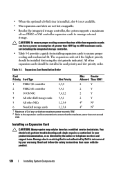
.... The expansion cards with the product. 120 Installing System Components All other NICs 1,2,3,4 41 N2 6 Non-Dell storage cards 1,2,3,4 41 N2 1 Maximum of 2 of any card whose maximum power exceeds 15W. 2 Refer... to the expansion card documentation to servicing that is not authorized by Dell is not available. • The expansion-card slots are not hot-swappable. • Besides the integrated storage... including the integrated storage controller. • Table 3-1 provides a guide for installing expansion cards to manage external storage.
.... The expansion cards with the product. 120 Installing System Components All other NICs 1,2,3,4 41 N2 6 Non-Dell storage cards 1,2,3,4 41 N2 1 Maximum of 2 of any card whose maximum power exceeds 15W. 2 Refer... to the expansion card documentation to servicing that is not authorized by Dell is not available. • The expansion-card slots are not hot-swappable. • Besides the integrated storage... including the integrated storage controller. • Table 3-1 provides a guide for installing expansion cards to manage external storage.

Hardware Owner's Manual
Page 121
... "Expansion Card Installation Guidelines." NOTE: Keep this bracket in case you need to their electrical outlets, and turn on riser 2 have card-edge guides for installing 24.13-cm (9.5-in) expansion cards. 1 Unpack the expansion card and prepare it for installation. The brackets also keep dust and dirt... out of the system. b Position the expansion card so that the card-edge connector aligns with the front card guide. See the documentation that slots 3 and 4 on the system. Filler brackets must be installed over empty expansion-card slots to maintain FCC ...
... "Expansion Card Installation Guidelines." NOTE: Keep this bracket in case you need to their electrical outlets, and turn on riser 2 have card-edge guides for installing 24.13-cm (9.5-in) expansion cards. 1 Unpack the expansion card and prepare it for installation. The brackets also keep dust and dirt... out of the system. b Position the expansion card so that the card-edge connector aligns with the front card guide. See the documentation that slots 3 and 4 on the system. Filler brackets must be installed over empty expansion-card slots to maintain FCC ...


