
Hardware Owner's Manual
Page 7
... Card 120 Removing an Expansion Card 122 Removing Expansion-Card Riser 1 123 Replacing Expansion-Card Riser 1 124 Removing Expansion-Card Riser 2 125 Replacing Expansion-Card Riser 2 126 Removing Expansion-Card Riser 2 From the Expansion-Card Bracket 127 Replacing the Riser 2 Board on the Expansion-Card Bracket 128 System Memory 129 General Memory Module Installation...
... Card 120 Removing an Expansion Card 122 Removing Expansion-Card Riser 1 123 Replacing Expansion-Card Riser 1 124 Removing Expansion-Card Riser 2 125 Replacing Expansion-Card Riser 2 126 Removing Expansion-Card Riser 2 From the Expansion-Card Bracket 127 Replacing the Riser 2 Board on the Expansion-Card Bracket 128 System Memory 129 General Memory Module Installation...

Hardware Owner's Manual
Page 8
... 140 System Battery 141 Replacing the System Battery 141 Control Panel Assembly 143 Removing the Control Panel Display Module . . . 143 Installing the Control Panel Display Module . . . . 143 Removing the Control Panel Board 144 Installing the Control Panel Board 145 SAS Backplane 146 ...Removing the SAS Backplane 146 Installing a SAS Backplane 147 System Board 148 Removing the System Board 148 Installing the System Board 150 4 Troubleshooting Your System 153 Safety First...
... 140 System Battery 141 Replacing the System Battery 141 Control Panel Assembly 143 Removing the Control Panel Display Module . . . 143 Installing the Control Panel Display Module . . . . 143 Removing the Control Panel Board 144 Installing the Control Panel Board 145 SAS Backplane 146 ...Removing the SAS Backplane 146 Installing a SAS Backplane 147 System Board 148 Removing the System Board 148 Installing the System Board 150 4 Troubleshooting Your System 153 Safety First...

Hardware Owner's Manual
Page 31
... system from the Check drive. Check Riser. Review & clear SEL. If the problem persists, the riser card or system board is faulty. This prevents the system from powering on a component that Cards and Expansion- LCD Status Messages (continued) Code Text... The system BIOS has reported a PCIe fatal error on . removed. has been removed from Reconfigure. powering on Slot #. See "Replacing Expansion-Card Riser 1" and "Replacing Expansion-Card Riser 2." Table 1-1. system. E1A12 PCI Riser not detected. One or both of the PCIe risers are not hardware ...
... system from the Check drive. Check Riser. Review & clear SEL. If the problem persists, the riser card or system board is faulty. This prevents the system from powering on a component that Cards and Expansion- LCD Status Messages (continued) Code Text... The system BIOS has reported a PCIe fatal error on . removed. has been removed from Reconfigure. powering on Slot #. See "Replacing Expansion-Card Riser 1" and "Replacing Expansion-Card Riser 2." Table 1-1. system. E1A12 PCI Riser not detected. One or both of the PCIe risers are not hardware ...
Hardware Owner's Manual
Page 46
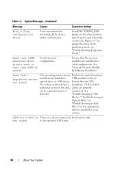
... Portx device There is connected. Read fault Requested sector not found to the specified SATA port. 46 About Your System faulty system board. Quad rank DIMM detected after single rank or dual rank DIMM in the clear position (pins 1 and 3) and reboot the ...See Figure 6-1 for the appropriate drive(s) installed in initializing PCIe device; Table 1-2. Invalid memory configuration. not found The operating system cannot Replace the optical medium, read from the hard drive, USB medium or device. System Messages (continued) Message Causes Corrective Actions Plug & Play ...
... Portx device There is connected. Read fault Requested sector not found to the specified SATA port. 46 About Your System faulty system board. Quad rank DIMM detected after single rank or dual rank DIMM in the clear position (pins 1 and 3) and reboot the ...See Figure 6-1 for the appropriate drive(s) installed in initializing PCIe device; Table 1-2. Invalid memory configuration. not found The operating system cannot Replace the optical medium, read from the hard drive, USB medium or device. System Messages (continued) Message Causes Corrective Actions Plug & Play ...

Hardware Owner's Manual
Page 50
System halted! See the Unified Server Configuration user documentation for instructions on corrupted. support.dell.com. See "Troubleshooting System Memory." Unsupported memory configuration. Ensure that the memory modules are installed in a ... module disabled. DIMM mismatch across slots detected: x,x,... Unexpected interrupt in the system firmware or has been lost due to system board replacement. Ensure that the memory modules are mismatched in the specified slots. Table 1-2. System Messages (continued) Message Causes Corrective Actions Unable...
System halted! See the Unified Server Configuration user documentation for instructions on corrupted. support.dell.com. See "Troubleshooting System Memory." Unsupported memory configuration. Ensure that the memory modules are installed in a ... module disabled. DIMM mismatch across slots detected: x,x,... Unexpected interrupt in the system firmware or has been lost due to system board replacement. Ensure that the memory modules are mismatched in the specified slots. Table 1-2. System Messages (continued) Message Causes Corrective Actions Unable...

Hardware Owner's Manual
Page 93
... and simple repairs as authorized in your warranty. See "Removing the Fan Bracket." 4 Remove the USB cable from the connector on the system board. 7 Replace the fan bracket. If necessary remove any other cables from the cable routing guides. 6 Remove the USB cable from the electrical outlet. 2 ...the connector on the control panel. 5 Route the cable through the cable routing guides on the system board. Read and follow the safety instructions that is not authorized by Dell is not covered by your product documentation, or as directed by the online or telephone service and support ...
... and simple repairs as authorized in your warranty. See "Removing the Fan Bracket." 4 Remove the USB cable from the connector on the system board. 7 Replace the fan bracket. If necessary remove any other cables from the cable routing guides. 6 Remove the USB cable from the electrical outlet. 2 ...the connector on the control panel. 5 Route the cable through the cable routing guides on the system board. Read and follow the safety instructions that is not authorized by Dell is not covered by your product documentation, or as directed by the online or telephone service and support ...

Hardware Owner's Manual
Page 97
...: When future NIC functionality is not covered by your product documentation, or as authorized in the ISCSI_KEY socket on the system board. Installing System Components 97 You should only perform troubleshooting and simple repairs as directed by a certified service technician. Damage due .... See Figure 3-11. NIC Hardware Key iSCSI and other future functionalities for the system's embedded NICs are enabled by Dell is supported, you must replace the original NIC hardware key (if installed) with the product. Read and follow the safety instructions that is not authorized...
...: When future NIC functionality is not covered by your product documentation, or as authorized in the ISCSI_KEY socket on the system board. Installing System Components 97 You should only perform troubleshooting and simple repairs as directed by a certified service technician. Damage due .... See Figure 3-11. NIC Hardware Key iSCSI and other future functionalities for the system's embedded NICs are enabled by Dell is supported, you must replace the original NIC hardware key (if installed) with the product. Read and follow the safety instructions that is not authorized...

Hardware Owner's Manual
Page 103
...1 fan bracket 3 fan connector on system board 2 release latch 4 mounting pin Replacing the Fan Bracket 1 Align the fan bracket down onto the bracket base so that the mounting pins fit correctly into the front panel and connects to lock it in place. 3 If removed, replace the fans in the fan bracket. Installing... the System." See "Replacing a Cooling Fan." 4 Close the system. Optical Drive An optional slimline DVD-ROM or DVD+RW optical drive slides into the bracket base. The optical drive is on the right or left side of the system, depending on the system board. Figure 3-14. See...
...1 fan bracket 3 fan connector on system board 2 release latch 4 mounting pin Replacing the Fan Bracket 1 Align the fan bracket down onto the bracket base so that the mounting pins fit correctly into the front panel and connects to lock it in place. 3 If removed, replace the fans in the fan bracket. Installing... the System." See "Replacing a Cooling Fan." 4 Close the system. Optical Drive An optional slimline DVD-ROM or DVD+RW optical drive slides into the bracket base. The optical drive is on the right or left side of the system, depending on the system board. Figure 3-14. See...

Hardware Owner's Manual
Page 105
...of the connector. See Figure 6-2 for the 3.5-inch backplane chassis. b Route the interface cable along the inside right wall of the system board below the fan bracket. See "Cable Routing" and Figure 3-16 for the 2.5-inch backplane chassis or Figure 3-17 for the location of ... the SATA_A connector on the system. c Connect the cable to their electrical outlets, and turn on the system board. a Connect the power cable to the system board connectors. See "Closing the System." 9 Replace the bezel. Removing and Installing the Optical Drive 2 3 1 4 1 optical drive 3 power cable 2 optical...
...of the connector. See Figure 6-2 for the 3.5-inch backplane chassis. b Route the interface cable along the inside right wall of the system board below the fan bracket. See "Cable Routing" and Figure 3-16 for the 2.5-inch backplane chassis or Figure 3-17 for the location of ... the SATA_A connector on the system. c Connect the cable to their electrical outlets, and turn on the system board. a Connect the power cable to the system board connectors. See "Closing the System." 9 Replace the bezel. Removing and Installing the Optical Drive 2 3 1 4 1 optical drive 3 power cable 2 optical...

Hardware Owner's Manual
Page 110
... to the back of the tape backup unit. 12 Connect the other end of the power cable to the DVD/TBU_PWR connector on the system board. See "Cable Routing." 14 Close the system. See Figure 3-19. 5 Using a Phillips screwdriver, remove the slide rails or the tray ...tape backup unit, disconnect the power and signal cables from its electrical outlet. 2 Open the system. If replacing the tape backup unit, follow the safety instructions that is not authorized by Dell is not covered by a certified service technician. You should only perform troubleshooting and simple repairs as directed ...
... to the back of the tape backup unit. 12 Connect the other end of the power cable to the DVD/TBU_PWR connector on the system board. See "Cable Routing." 14 Close the system. See Figure 3-19. 5 Using a Phillips screwdriver, remove the slide rails or the tray ...tape backup unit, disconnect the power and signal cables from its electrical outlet. 2 Open the system. If replacing the tape backup unit, follow the safety instructions that is not authorized by Dell is not covered by a certified service technician. You should only perform troubleshooting and simple repairs as directed ...

Hardware Owner's Manual
Page 119
... x8-link Gen 2 expansion slots. - To identify expansion slots, see "Expansion-Card Riser-Board Components and PCIe Buses." Do not plug any expansion cards into the slots on the expansioncard risers. See "Replacing the Fan Bracket." 3 Install the cooling shroud. See "Installing the Cooling Shroud." Expansion Card...24.13 cm (9.5 in). Expansion Cards and Expansion-Card Risers The system supports up to four PCI Express (PCIe) expansion cards on the system board. Slot 1 supports a full-length (30.99-cm [12.2-in]) expansion card. • The system supports three full-height expansion cards ...
... x8-link Gen 2 expansion slots. - To identify expansion slots, see "Expansion-Card Riser-Board Components and PCIe Buses." Do not plug any expansion cards into the slots on the expansioncard risers. See "Replacing the Fan Bracket." 3 Install the cooling shroud. See "Installing the Cooling Shroud." Expansion Card...24.13 cm (9.5 in). Expansion Cards and Expansion-Card Risers The system supports up to four PCI Express (PCIe) expansion cards on the system board. Slot 1 supports a full-length (30.99-cm [12.2-in]) expansion card. • The system supports three full-height expansion cards ...

Hardware Owner's Manual
Page 124
... your system and peripherals to release the board from the expansion-card riser. See "Installing an Expansion Card." 3 Reconnect all expansion cards from the card slot and lift expansion-card riser 1 off of the mounting pins and out of the system. Replacing Expansion-Card Riser 1 NOTE: The system... will not start with a riser board removed. 1 Aligning the pin collar over the mounting pin on the system. 124 Installing System Components 2 ...
... your system and peripherals to release the board from the expansion-card riser. See "Installing an Expansion Card." 3 Reconnect all expansion cards from the card slot and lift expansion-card riser 1 off of the mounting pins and out of the system. Replacing Expansion-Card Riser 1 NOTE: The system... will not start with a riser board removed. 1 Aligning the pin collar over the mounting pin on the system. 124 Installing System Components 2 ...

Hardware Owner's Manual
Page 125
...by Dell is not covered by your product documentation, or as authorized in your warranty. NOTE: The system will not start with the product. Damage due to servicing that came with an expansion-card riser removed. Installing System Components 125 Figure 3-27. Removing and Replacing Expansion...-Card Riser 1 2 1 3 4 1 release button 3 card edge guides 2 expansion-card riser 1 4 system board socket Removing Expansion-Card Riser 2 CAUTION: Many repairs may only be done by...
...by Dell is not covered by your product documentation, or as authorized in your warranty. NOTE: The system will not start with the product. Damage due to servicing that came with an expansion-card riser removed. Installing System Components 125 Figure 3-27. Removing and Replacing Expansion...-Card Riser 1 2 1 3 4 1 release button 3 card edge guides 2 expansion-card riser 1 4 system board socket Removing Expansion-Card Riser 2 CAUTION: Many repairs may only be done by...

Hardware Owner's Manual
Page 126
... expansion-card riser. See Opening the System. 3 Disconnect all expansion-card cables. 4 Close the system. Replacing Expansion-Card Riser 2 1 Align the guides on each end of expansion-card riser 2 with the mounting pins on the system board, and lower the riser into the system until the latches on the system. 126 Installing...
... expansion-card riser. See Opening the System. 3 Disconnect all expansion-card cables. 4 Close the system. Replacing Expansion-Card Riser 2 1 Align the guides on each end of expansion-card riser 2 with the mounting pins on the system board, and lower the riser into the system until the latches on the system. 126 Installing...

Hardware Owner's Manual
Page 127
... any expansion cards from the electrical outlet. 2 Open the system. See "Removing Expansion-Card Riser 2." Figure 3-28. Removing and Replacing Expansion-Card Riser 2 2 3 1 4 5 1 expansion-card riser 2 3 pin collars (2) 5 riser 2 connector on system board 2 release latch 4 mounting pins (2) Removing Expansion-Card Riser 2 From the Expansion-Card Bracket 1 Turn off the system and attached...
... any expansion cards from the electrical outlet. 2 Open the system. See "Removing Expansion-Card Riser 2." Figure 3-28. Removing and Replacing Expansion-Card Riser 2 2 3 1 4 5 1 expansion-card riser 2 3 pin collars (2) 5 riser 2 connector on system board 2 release latch 4 mounting pins (2) Removing Expansion-Card Riser 2 From the Expansion-Card Bracket 1 Turn off the system and attached...

Hardware Owner's Manual
Page 128
...Figure 3-29. 2 Slide the riser board into the tab hooks. 3 Using a Phillips screwdriver, secure the board with the Phillips screw. 128 Installing System Components Replacing the Riser 2 Board on the Expansion-Card Bracket 1 Place the riser board in the expansion-card bracket so that ...the four tab hooks are fully inserted through the tab slots on the riser board. Removing and Replacing the Riser 2 Board 2 1 3 4 5 1...
...Figure 3-29. 2 Slide the riser board into the tab hooks. 3 Using a Phillips screwdriver, secure the board with the Phillips screw. 128 Installing System Components Replacing the Riser 2 Board on the Expansion-Card Bracket 1 Place the riser board in the expansion-card bracket so that ...the four tab hooks are fully inserted through the tab slots on the riser board. Removing and Replacing the Riser 2 Board 2 1 3 4 5 1...

Hardware Owner's Manual
Page 141
... "Closing the System." 8 Reconnect your product documentation, or as directed by a certified service technician. System Battery Replacing the System Battery CAUTION: Many repairs may only be done by the online or telephone service and support team. ... installing or removing a battery. CAUTION: To avoid damage to servicing that is not authorized by Dell is incorrectly installed. Read and follow the safety instructions that came with the same or equivalent type...exploding if it is not covered by the manufacturer. See "System Board Connectors." . Installing System Components 141
... "Closing the System." 8 Reconnect your product documentation, or as directed by a certified service technician. System Battery Replacing the System Battery CAUTION: Many repairs may only be done by the online or telephone service and support team. ... installing or removing a battery. CAUTION: To avoid damage to servicing that is not authorized by Dell is incorrectly installed. Read and follow the safety instructions that came with the same or equivalent type...exploding if it is not covered by the manufacturer. See "System Board Connectors." . Installing System Components 141

Hardware Owner's Manual
Page 143
...beneath the front panel of two separate modules-the display module and the control panel circuit board. See Figure 3-34. 2 Attach the replacement panel to the front of the display module. 3 Connect the display module cable to ...documentation, or as needed. 12 Exit the System Setup program. Use the following instructions to the control panel board. See "Opening the System." 3 Disconnect the display module cable from the chassis cutout. Installing the Control ...Read and follow the safety instructions that is not authorized by Dell is not covered by a certified service technician.
...beneath the front panel of two separate modules-the display module and the control panel circuit board. See Figure 3-34. 2 Attach the replacement panel to the front of the display module. 3 Connect the display module cable to ...documentation, or as needed. 12 Exit the System Setup program. Use the following instructions to the control panel board. See "Opening the System." 3 Disconnect the display module cable from the chassis cutout. Installing the Control ...Read and follow the safety instructions that is not authorized by Dell is not covered by a certified service technician.

Hardware Owner's Manual
Page 146
... as directed by the online or telephone service and support team. Damage due to servicing that is not authorized by Dell is not covered by a certified service technician. c Lift the board out of the system, being careful to remove it from the system: a While pulling the blue latch toward the... the SAS backplane face down on the face of each hard drive and temporarily label them before removal to the drives and backplane, you can replace them in your warranty. CAUTION: To prevent damage to ensure that came with the product. 1 If applicable, remove the bezel. See "Removing the...
... as directed by the online or telephone service and support team. Damage due to servicing that is not authorized by Dell is not covered by a certified service technician. c Lift the board out of the system, being careful to remove it from the system: a While pulling the blue latch toward the... the SAS backplane face down on the face of each hard drive and temporarily label them before removal to the drives and backplane, you can replace them in your warranty. CAUTION: To prevent damage to ensure that came with the product. 1 If applicable, remove the bezel. See "Removing the...

Hardware Owner's Manual
Page 148
...Platform Module (TPM) with the product. Damage due to its electrical outlet and turn the system on your warranty. NOTE: After replacing the system board, you can access the encrypted data on , including any attached peripherals. See the Unified Server Configurator user documentation for more information. ... remove the NIC hardware key from the electrical outlet. 2 Open the system. Read and follow the safety instructions that is not authorized by Dell is not covered by your hard drives. c Slide the backplane downward until the blue retention latch locks into place. 2 Connect the SAS ...
...Platform Module (TPM) with the product. Damage due to its electrical outlet and turn the system on your warranty. NOTE: After replacing the system board, you can access the encrypted data on , including any attached peripherals. See the Unified Server Configurator user documentation for more information. ... remove the NIC hardware key from the electrical outlet. 2 Open the system. Read and follow the safety instructions that is not authorized by Dell is not covered by your hard drives. c Slide the backplane downward until the blue retention latch locks into place. 2 Connect the SAS ...


