
Hardware Owner's Manual
Page 88
... supply blank in your product documentation, or as authorized in the bay by a certified service technician. Damage due to servicing that is not authorized by Dell is functioning properly (see Figure 1-6). Remove the power supply blank only if you are installing a second power supply. Installing the Power Supply Blank NOTE: Install...: To ensure proper system cooling, the power supply blank must be done by pulling outward on the chassis, then lower the opposite edge of the tray fit into the hooks on the blank.
... supply blank in your product documentation, or as authorized in the bay by a certified service technician. Damage due to servicing that is not authorized by Dell is functioning properly (see Figure 1-6). Remove the power supply blank only if you are installing a second power supply. Installing the Power Supply Blank NOTE: Install...: To ensure proper system cooling, the power supply blank must be done by pulling outward on the chassis, then lower the opposite edge of the tray fit into the hooks on the blank.
Hardware Owner's Manual
Page 90
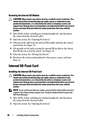
...technician. See "Closing the System." 6 Reconnect the system and peripherals to the chassis, then lift the tray out of the chassis. Damage due to servicing that is not authorized by Dell is not covered by your product documentation, or as authorized in the System Setup program. See "Using...including any attached peripherals, and disconnect the system from the control panel board. You should only perform troubleshooting and simple repairs as directed by Dell is enabled in your warranty. NOTE: To use an SD card with the product. 1 Turn off the system, including any attached ...
...technician. See "Closing the System." 6 Reconnect the system and peripherals to the chassis, then lift the tray out of the chassis. Damage due to servicing that is not authorized by Dell is not covered by your product documentation, or as authorized in the System Setup program. See "Using...including any attached peripherals, and disconnect the system from the control panel board. You should only perform troubleshooting and simple repairs as directed by Dell is enabled in your warranty. NOTE: To use an SD card with the product. 1 Turn off the system, including any attached ...

Hardware Owner's Manual
Page 104
... tab at the back of the optical drive and push the drive out of the drive tray. 104 Installing System Components Read and follow the safety instructions that is not authorized by Dell is not covered by your warranty. See Figure 3-15. See "Opening the System." 3...Disconnect the optical drive cable from its electrical outlet. 2 Open the system. Read and follow the safety instructions that is not authorized by Dell is not covered by your warranty. Installing the Optical Drive CAUTION: Many repairs may only be done by a certified service technician. You should...
... tab at the back of the optical drive and push the drive out of the drive tray. 104 Installing System Components Read and follow the safety instructions that is not authorized by Dell is not covered by your warranty. See Figure 3-15. See "Opening the System." 3...Disconnect the optical drive cable from its electrical outlet. 2 Open the system. Read and follow the safety instructions that is not authorized by Dell is not covered by your warranty. Installing the Optical Drive CAUTION: Many repairs may only be done by a certified service technician. You should...

Hardware Owner's Manual
Page 108
See Figure 3-18. 5 For a SCSI tape drive, route the SCSI data and power cables through the flex bay and through the tray and connect the cables to servicing that came with the product. 1 Turn off the system, including any attached peripherals, and disconnect the system from... warranty. Read and follow the safety instructions that is not authorized by Dell is not covered by squeezing the blue release tabs at the back of the tray and pushing the tray out of the system. 4 Using a Phillips screwdriver, disassemble the blank tray: • For 2.5-inch hard-drive systems, remove the slide rails...
See Figure 3-18. 5 For a SCSI tape drive, route the SCSI data and power cables through the flex bay and through the tray and connect the cables to servicing that came with the product. 1 Turn off the system, including any attached peripherals, and disconnect the system from... warranty. Read and follow the safety instructions that is not authorized by Dell is not covered by squeezing the blue release tabs at the back of the tray and pushing the tray out of the system. 4 Using a Phillips screwdriver, disassemble the blank tray: • For 2.5-inch hard-drive systems, remove the slide rails...

Hardware Owner's Manual
Page 109
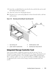
Preparing the Tape Backup Unit and Tray (3.5-in one of the tape backup unit. See "Installing an Expansion Card." 9 Connect the power cable to the power connector on the tape backup unit. ... backup unit, install the SCSI controller expansion card in HDD Chassis Only) 2 3 1 4 1 drive blank 3 tray 2 screws (4) 4 tape backup unit 6 Install the slide rails or tray on the back of the expansion-card slots. Figure 3-18 shows the 3.5-inch tray installation. 7 Align the tape backup unit with the flex bay and slide the unit...
Preparing the Tape Backup Unit and Tray (3.5-in one of the tape backup unit. See "Installing an Expansion Card." 9 Connect the power cable to the power connector on the tape backup unit. ... backup unit, install the SCSI controller expansion card in HDD Chassis Only) 2 3 1 4 1 drive blank 3 tray 2 screws (4) 4 tape backup unit 6 Install the slide rails or tray on the back of the expansion-card slots. Figure 3-18 shows the 3.5-inch tray installation. 7 Align the tape backup unit with the flex bay and slide the unit...

Hardware Owner's Manual
Page 110
...authorized in "Installing the Tape Backup Unit." 110 Installing System Components See Figure 3-19. 5 Using a Phillips screwdriver, remove the slide rails or the tray from the tape backup unit. 6 For a SCSI tape backup unit, disconnect the power and signal cables from its electrical outlet. 2 Open the system.... "Closing the System." 15 Reconnect your warranty. If replacing the tape backup unit, follow the safety instructions that is not authorized by Dell is not covered by your system and peripherals to their electrical outlets, and turn on the system board. See Figure 6-2 for the ...
...authorized in "Installing the Tape Backup Unit." 110 Installing System Components See Figure 3-19. 5 Using a Phillips screwdriver, remove the slide rails or the tray from the tape backup unit. 6 For a SCSI tape backup unit, disconnect the power and signal cables from its electrical outlet. 2 Open the system.... "Closing the System." 15 Reconnect your warranty. If replacing the tape backup unit, follow the safety instructions that is not authorized by Dell is not covered by your system and peripherals to their electrical outlets, and turn on the system board. See Figure 6-2 for the ...
Hardware Owner's Manual
Page 111
...outlets, and turn on riser 1 for an integrated storage controller card that provides the storage subsystem for optical drive 2 interface/power cable 4 mounting tray release tab (2) Integrated Storage Controller Card Your system includes a dedicated expansion-card slot on the system. 8 Insert the assembled blank... tray into the flex bay and slide the unit in RAID configurations as supported by the version of the storage controller included with your ...
...outlets, and turn on riser 1 for an integrated storage controller card that provides the storage subsystem for optical drive 2 interface/power cable 4 mounting tray release tab (2) Integrated Storage Controller Card Your system includes a dedicated expansion-card slot on the system. 8 Insert the assembled blank... tray into the flex bay and slide the unit in RAID configurations as supported by the version of the storage controller included with your ...

Hardware Owner's Manual
Page 149
... from the chassis. a Remove all cables from the SAS backplane. See Figure 3-35. c Pull the blue latch toward the front end of the system board tray, and lift the assembly from the retention hooks. Installing System Components 149 WARNING: Do not lift the system board by the edges of the chassis...
... from the chassis. a Remove all cables from the SAS backplane. See Figure 3-35. c Pull the blue latch toward the front end of the system board tray, and lift the assembly from the retention hooks. Installing System Components 149 WARNING: Do not lift the system board by the edges of the chassis...
Hardware Owner's Manual
Page 150
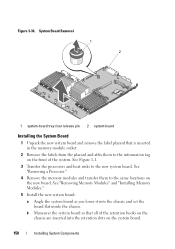
... the memory module socket. 2 Remove the labels from the placard and affix them to the new system board. Figure 3-36. System Board Removal 1 2 1 system-board tray riser release pin 2 system board Installing the System Board 1 Unpack the new system board and remove the label placard that all of the retention hooks...
... the memory module socket. 2 Remove the labels from the placard and affix them to the new system board. Figure 3-36. System Board Removal 1 2 1 system-board tray riser release pin 2 system board Installing the System Board 1 Unpack the new system board and remove the label placard that all of the retention hooks...