
Glossary
Page 1
... Configuration and Power Interface. cm - ACPI - The temperature of a program or data file. ANSI - The modules are mounted into a chassis that is located. A CD, diskette, or USB memory key that includes power supplies and fans. bus - cache - As a precaution,...Your system also contains an address bus and a data bus for developing technology standards in the U.S. AC - Baseboard management controller. Dell™ Glossary NOTE: For additional information on storage terminology, visit the Storage Networking Industry Association's website at www.snia.org and...
... Configuration and Power Interface. cm - ACPI - The temperature of a program or data file. ANSI - The modules are mounted into a chassis that is located. A CD, diskette, or USB memory key that includes power supplies and fans. bus - cache - As a precaution,...Your system also contains an address bus and a data bus for developing technology standards in the U.S. AC - Baseboard management controller. Dell™ Glossary NOTE: For additional information on storage terminology, visit the Storage Networking Industry Association's website at www.snia.org and...

Information Update - Intel Xeon 5600 Series Processors
Page 1
... set of Intel Xeon 5600 series processors: - M710 NOTE: The PowerEdge R410, T410, and R510 systems do not support 130 W Intel Xeon 5600 series processors. R610 - T710 - December 2010 R710 - NOTE: The PowerEdge R610 and M710 systems need specific heat sinks to support Intel Xeon ...and 5600 series processors is not supported. • Systems with the Roman Numeral II on the chassis support the complete feature set of the Intel Xeon 5600 series processor. • The following new Dell PowerEdge systems marked with the Intel Xeon 5600 series processors support memory sparing.
... set of Intel Xeon 5600 series processors: - M710 NOTE: The PowerEdge R410, T410, and R510 systems do not support 130 W Intel Xeon 5600 series processors. R610 - T710 - December 2010 R710 - NOTE: The PowerEdge R610 and M710 systems need specific heat sinks to support Intel Xeon ...and 5600 series processors is not supported. • Systems with the Roman Numeral II on the chassis support the complete feature set of the Intel Xeon 5600 series processor. • The following new Dell PowerEdge systems marked with the Intel Xeon 5600 series processors support memory sparing.

Hardware Owner's Manual
Page 12
Front-Panel Features and Indicators (3.5-Inch Chassis) 1 2 3 45 67 8 9 10 12 About Your System Front-Panel Features and Indicators (2.5-Inch Chassis) 1 2 3 45 67 8 9 10 11 Figure 1-2. Front-Panel Features and Indicators Figure 1-1.
Front-Panel Features and Indicators (3.5-Inch Chassis) 1 2 3 45 67 8 9 10 12 About Your System Front-Panel Features and Indicators (2.5-Inch Chassis) 1 2 3 45 67 8 9 10 11 Figure 1-2. Front-Panel Features and Indicators Figure 1-1.
Hardware Owner's Manual
Page 14
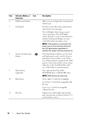
... tape backup unit (not present on the front and back panels can be used to navigate the control panel LCD menu. The identification buttons on chassis with six 3.5inch hard-drive slots) 14 About Your System Provides system ID, status information, and system error messages. Item Indicator, Button, or Icon Connector...
... tape backup unit (not present on the front and back panels can be used to navigate the control panel LCD menu. The identification buttons on chassis with six 3.5inch hard-drive slots) 14 About Your System Provides system ID, status information, and system error messages. Item Indicator, Button, or Icon Connector...
Hardware Owner's Manual
Page 35
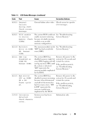
... has Remove AC power to the disabled memory single-bit system for specific error messages. memory module implicated by the BIOS. Power cycle AC. Check chassis cover. About Your System 35 General failure after video. The memory module in slot See "Troubleshooting "##" has had too many errors. see "Troubleshooting System Memory...
... has Remove AC power to the disabled memory single-bit system for specific error messages. memory module implicated by the BIOS. Power cycle AC. Check chassis cover. About Your System 35 General failure after video. The memory module in slot See "Troubleshooting "##" has had too many errors. see "Troubleshooting System Memory...

Hardware Owner's Manual
Page 76
Inside the System (2.5-Inch Hard-Drive Chassis) 6 5 4 3 2 1 7 8 9 16 15 14 13 12 10 11 1 USB connector for optional internal USB key 3 hot-swappable cooling fans (4 or 5) 5 processors (1 or 2) 7 riser 2 (PCIe slots 3 and 4) 9 ...
Inside the System (2.5-Inch Hard-Drive Chassis) 6 5 4 3 2 1 7 8 9 16 15 14 13 12 10 11 1 USB connector for optional internal USB key 3 hot-swappable cooling fans (4 or 5) 5 processors (1 or 2) 7 riser 2 (PCIe slots 3 and 4) 9 ...

Hardware Owner's Manual
Page 78
... location of the information tag slot. 3 Pull down on the tag until it disengages from the slot in the chassis to release the top portion of the tag. 4 Pull up on the front of the system chassis. See "Removing the Front Bezel." 2 Pull the information tag out of its slot in the... chassis until it disengages from the slot in the chassis to engage the latch. Installing the Front Bezel 1 Insert the hinge tab on...
... location of the information tag slot. 3 Pull down on the tag until it disengages from the slot in the chassis to release the top portion of the tag. 4 Pull up on the front of the system chassis. See "Removing the Front Bezel." 2 Pull the information tag out of its slot in the... chassis until it disengages from the slot in the chassis to engage the latch. Installing the Front Bezel 1 Insert the hinge tab on...

Hardware Owner's Manual
Page 79
...See Figure 3-3. 3 Lift up the latch on the cover. 2 Place the cover onto the chassis and offset the cover slightly back so that it clears the chassis hooks and lays flush on the system chassis. Opening and Closing the System CAUTION: Many repairs may only be done by the online or...cover into the closed position. 4 Rotate the latch release lock in your warranty. Read and follow the safety instructions that is not authorized by Dell is not covered by your product documentation, or as authorized in a clockwise direction to lift the system by yourself. You should only perform ...
...See Figure 3-3. 3 Lift up the latch on the cover. 2 Place the cover onto the chassis and offset the cover slightly back so that it clears the chassis hooks and lays flush on the system chassis. Opening and Closing the System CAUTION: Many repairs may only be done by the online or...cover into the closed position. 4 Rotate the latch release lock in your warranty. Read and follow the safety instructions that is not authorized by Dell is not covered by your product documentation, or as authorized in a clockwise direction to lift the system by yourself. You should only perform ...
Hardware Owner's Manual
Page 80
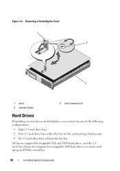
Figure 3-3. Removing or Installing the Cover 1 2 3 1 latch 3 chassis hooks 2 latch release lock Hard Drives Depending on your chassis and backplane, your system has one of the following configurations: • Eight 2.5-inch drive bays • Four 3.5-inch drive bays with a flex bay for the optional tape backup unit • Six 3.5-inch drive bays without the flex bay All chassis support hot-swappable SAS and SATA hard drives, and the 2.5inch-bay chassis also supports hot-swappable SSD hard drives in systems with integrated PERC controllers. 80 Installing System Components
Figure 3-3. Removing or Installing the Cover 1 2 3 1 latch 3 chassis hooks 2 latch release lock Hard Drives Depending on your chassis and backplane, your system has one of the following configurations: • Eight 2.5-inch drive bays • Four 3.5-inch drive bays with a flex bay for the optional tape backup unit • Six 3.5-inch drive bays without the flex bay All chassis support hot-swappable SAS and SATA hard drives, and the 2.5inch-bay chassis also supports hot-swappable SSD hard drives in systems with integrated PERC controllers. 80 Installing System Components

Hardware Owner's Manual
Page 81
... hot-swap drive removal and insertion. All drives are installed at the front of SAS and SATA drives are also supported in the 3.5-inch-bay chassis only. Hard drives are supplied in special hotswappable hard-drive carriers that the host adapter is running, see "Front-Panel Features and Indicators"). In this...
... hot-swap drive removal and insertion. All drives are installed at the front of SAS and SATA drives are also supported in the 3.5-inch-bay chassis only. Hard drives are supplied in special hotswappable hard-drive carriers that the host adapter is running, see "Front-Panel Features and Indicators"). In this...

Hardware Owner's Manual
Page 86
... management arm if it must be installed in the PS2 bay in a non-redundant configuration. NOTE: The system does not support a mixed installation of the chassis. See "Installing the Power Supply Blank." Swapping the opposite power supply to an Energy Smart configuration or vice versa, you intend to remove and remove...
... management arm if it must be installed in the PS2 bay in a non-redundant configuration. NOTE: The system does not support a mixed installation of the chassis. See "Installing the Power Supply Blank." Swapping the opposite power supply to an Energy Smart configuration or vice versa, you intend to remove and remove...

Hardware Owner's Manual
Page 87
... 87 NOTE: If you unlatched the cable management arm in watts) is listed on the power supply label. 2 Slide the new power supply into the chassis until the power supply is fully seated and the release latch snaps into a power outlet. CAUTION: When connecting the power cable, secure the cable with...
... 87 NOTE: If you unlatched the cable management arm in watts) is listed on the power supply label. 2 Slide the new power supply into the chassis until the power supply is fully seated and the release latch snaps into a power outlet. CAUTION: When connecting the power cable, secure the cable with...

Hardware Owner's Manual
Page 88
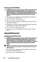
...as authorized in a non-redundant configuration. Read and follow the safety instructions that came with the power supply bay and insert it into the chassis until it clicks into the hooks on the blank. See "Opening the System." 3 Position the module so the tabs on the underside of ...signify that is not authorized by a certified service technician. CAUTION: To ensure proper system cooling, the power supply blank must be done by Dell is functioning properly (see Figure 1-6). Internal SD Module Installing the Internal SD Module CAUTION: Many repairs may only be installed in the second ...
...as authorized in a non-redundant configuration. Read and follow the safety instructions that came with the power supply bay and insert it into the chassis until it clicks into the hooks on the blank. See "Opening the System." 3 Position the module so the tabs on the underside of ...signify that is not authorized by a certified service technician. CAUTION: To ensure proper system cooling, the power supply blank must be done by Dell is functioning properly (see Figure 1-6). Internal SD Module Installing the Internal SD Module CAUTION: Many repairs may only be installed in the second ...
Hardware Owner's Manual
Page 90
...may only be done by your warranty. Read and follow the safety instructions that came with your system, ensure that is not authorized by Dell is not covered by a certified service technician. See "Opening the System." 90 Installing System Components See "Opening the System." 3 Disconnect...the safety instructions that is not authorized by the online or telephone service and support team. Damage due to the chassis, then lift the tray out of the chassis. See "Using the System Setup Program and UEFI Boot Manager." 1 Turn off the system, including any attached ...
...may only be done by your warranty. Read and follow the safety instructions that came with your system, ensure that is not authorized by Dell is not covered by a certified service technician. See "Opening the System." 90 Installing System Components See "Opening the System." 3 Disconnect...the safety instructions that is not authorized by the online or telephone service and support team. Damage due to the chassis, then lift the tray out of the chassis. See "Using the System Setup Program and UEFI Boot Manager." 1 Turn off the system, including any attached ...

Hardware Owner's Manual
Page 93
... only perform troubleshooting and simple repairs as authorized in your warranty. Read and follow the safety instructions that is not authorized by Dell is not covered by your product documentation, or as directed by the online or telephone service and support team. Read and follow... the product. 1 Turn off the system, including any attached peripherals, and disconnect the system from the connector on the inside of the chassis. Internal USB Cable Removing the Internal USB Cable CAUTION: Many repairs may only be done by a certified service technician. You should only...
... only perform troubleshooting and simple repairs as authorized in your warranty. Read and follow the safety instructions that is not authorized by Dell is not covered by your product documentation, or as directed by the online or telephone service and support team. Read and follow... the product. 1 Turn off the system, including any attached peripherals, and disconnect the system from the connector on the inside of the chassis. Internal USB Cable Removing the Internal USB Cable CAUTION: Many repairs may only be done by a certified service technician. You should only...
Hardware Owner's Manual
Page 100
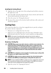
... started. 1 Open the system. NOTE: If a fan is on. NOTE: In the event of the shroud into the chassis cutouts and rotate the left end down inside the left chassis wall. 3 Close the system. Read and follow the safety instructions that is not authorized by your product documentation, or as...fan will still be done by the online or telephone service and support team. To maintain proper cooling while the system is not covered by Dell is on the system and attached peripherals. You should only perform troubleshooting and simple repairs as authorized in the fan 5 bay. Damage due ...
... started. 1 Open the system. NOTE: If a fan is on. NOTE: In the event of the shroud into the chassis cutouts and rotate the left end down inside the left chassis wall. 3 Close the system. Read and follow the safety instructions that is not authorized by your product documentation, or as...fan will still be done by the online or telephone service and support team. To maintain proper cooling while the system is not covered by Dell is on the system and attached peripherals. You should only perform troubleshooting and simple repairs as authorized in the fan 5 bay. Damage due ...

Hardware Owner's Manual
Page 103
See "Replacing a Cooling Fan." 4 Close the system. See "Closing the System." Removing and Installing the Processor Fan Bracket 1 2 4 3 1 fan bracket 3 fan connector on your chassis. The optical drive is on the right or left side of the system, depending on system board 2 release latch 4 mounting pin Replacing the Fan Bracket 1 ...
See "Replacing a Cooling Fan." 4 Close the system. See "Closing the System." Removing and Installing the Processor Fan Bracket 1 2 4 3 1 fan bracket 3 fan connector on your chassis. The optical drive is on the right or left side of the system, depending on system board 2 release latch 4 mounting pin Replacing the Fan Bracket 1 ...

Hardware Owner's Manual
Page 105
...cable 2 optical-drive interface cable 4 optical-drive release tab Installing System Components 105 See "Cable Routing" and Figure 3-16 for the 2.5-inch backplane chassis or Figure 3-17 for the location of the system board below the fan bracket. See Figure 6-2 for the 3.5-inch backplane... chassis. See Figure 6-2 for the location of the chassis. c Connect the cable to their electrical outlets, and turn on the system board. See "Installing the Front Bezel." 10 Reconnect ...
...cable 2 optical-drive interface cable 4 optical-drive release tab Installing System Components 105 See "Cable Routing" and Figure 3-16 for the 2.5-inch backplane chassis or Figure 3-17 for the location of the system board below the fan bracket. See Figure 6-2 for the 3.5-inch backplane... chassis. See Figure 6-2 for the location of the chassis. c Connect the cable to their electrical outlets, and turn on the system board. See "Installing the Front Bezel." 10 Reconnect ...
Hardware Owner's Manual
Page 106
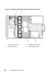
Figure 3-16. Routing the Optical Drive Cable (2.5-inch Hard-Drive Chassis) 1 2 1 optical drive connector 3 SATA_A connector 4 3 2 DVD/TBU_PWR connector 4 cable retention bracket 106 Installing System Components
Figure 3-16. Routing the Optical Drive Cable (2.5-inch Hard-Drive Chassis) 1 2 1 optical drive connector 3 SATA_A connector 4 3 2 DVD/TBU_PWR connector 4 cable retention bracket 106 Installing System Components

Hardware Owner's Manual
Page 107
...on the system board for a SATA device, or to the SCSI controller expansion card for a SCSI device. Routing the Optical Drive Cable (3.5-inch Hard-Drive Chassis) 1 2 3 4 1 optical drive connector 3 cable retention bracket 2 DVD/TBU_PWR connector 4 SATA_A connector Internal Tape Backup Unit An optional internal tape ... the Tape Backup Unit CAUTION: Many repairs may only be installed in your product documentation, or as authorized in a chassis that has a flex bay. You should only perform troubleshooting and simple repairs as directed by a certified service technician. Figure 3-17.
...on the system board for a SATA device, or to the SCSI controller expansion card for a SCSI device. Routing the Optical Drive Cable (3.5-inch Hard-Drive Chassis) 1 2 3 4 1 optical drive connector 3 cable retention bracket 2 DVD/TBU_PWR connector 4 SATA_A connector Internal Tape Backup Unit An optional internal tape ... the Tape Backup Unit CAUTION: Many repairs may only be installed in your product documentation, or as authorized in a chassis that has a flex bay. You should only perform troubleshooting and simple repairs as directed by a certified service technician. Figure 3-17.


