Information Update - System Memory
Page 2
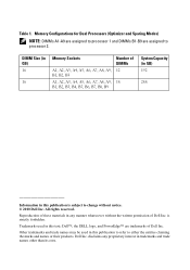
... of these materials in any proprietary interest in this publication to refer to processor 2. Trademarks used in this text: Dell™, the DELL logo, and PowerEdge™ are assigned to either the entities claiming the marks and names or their products. Other trademarks and trade names... may be used in this publication is strictly forbidden. Dell Inc. All rights reserved. DIMM Size (in GB) 16 16 Memory Sockets A1, A2, ...
... of these materials in any proprietary interest in this publication to refer to processor 2. Trademarks used in this text: Dell™, the DELL logo, and PowerEdge™ are assigned to either the entities claiming the marks and names or their products. Other trademarks and trade names... may be used in this publication is strictly forbidden. Dell Inc. All rights reserved. DIMM Size (in GB) 16 16 Memory Sockets A1, A2, ...

Information Update - Processor Installation
Page 4
... lever and release the lever from the locked position by pushing down and pulling out from the socket. CAUTION: The processor is released from under strong pressure. See Figure 1-2. 4 Processor Installation Figure 1-1. Be aware that the release lever can spring ...not firmly grasped. 9 Position your Hardware Owner's Manual for a system-specific illustration. Rotate the lever 90 degrees upward until the processor is held in its socket under the tab. Installing and Removing the Heat Sink 2 1 1 heat sink 2 release lever (2) NOTE: Your heat sink may appear differently than the ...
... lever and release the lever from the locked position by pushing down and pulling out from the socket. CAUTION: The processor is released from under strong pressure. See Figure 1-2. 4 Processor Installation Figure 1-1. Be aware that the release lever can spring ...not firmly grasped. 9 Position your Hardware Owner's Manual for a system-specific illustration. Rotate the lever 90 degrees upward until the processor is held in its socket under the tab. Installing and Removing the Heat Sink 2 1 1 heat sink 2 release lever (2) NOTE: Your heat sink may appear differently than the ...

Information Update - Processor Installation
Page 5
...or temporary storage. After removing the processor, place it in the CPU2 socket to installing a processor. Touch only the side edges of the socket and leave the release lever up so that the socket is similar to ensure proper system cooling. If you are permanently removing ...permanently damage the system board. 11 Carefully, lift the processor out of the processor. Removing a Processor 2 3 1 4 1 socket-release lever 3 processor shield 2 processor 4 ZIF socket CAUTION: Be careful not to bend any of the processor. Processor Installation 5 Do not touch the bottom of the pins on the...
...or temporary storage. After removing the processor, place it in the CPU2 socket to installing a processor. Touch only the side edges of the socket and leave the release lever up so that the socket is similar to ensure proper system cooling. If you are permanently removing ...permanently damage the system board. 11 Carefully, lift the processor out of the processor. Removing a Processor 2 3 1 4 1 socket-release lever 3 processor shield 2 processor 4 ZIF socket CAUTION: Be careful not to bend any of the processor. Processor Installation 5 Do not touch the bottom of the pins on the...

Information Update - Processor Installation
Page 6
...similar to seat the processor. Keep the processor level (see Figure 1-3) and insert it in the socket. 5 Place the processor over the socket with the system. Handle the processor carefully with the socket keys on the top of the components inside the system. See Figure 1-3 and Figure 1-4. CAUTION... heatsink blank and the processor blank from the packing material by the processor's edges only. NOTE: In a single-processor configuration, the CPU1 socket must be used. 1 If you are authorized to float on the side edges. See Figure 1-4. Allow the processor to remove the system ...
...similar to seat the processor. Keep the processor level (see Figure 1-3) and insert it in the socket. 5 Place the processor over the socket with the system. Handle the processor carefully with the socket keys on the top of the components inside the system. See Figure 1-3 and Figure 1-4. CAUTION... heatsink blank and the processor blank from the packing material by the processor's edges only. NOTE: In a single-processor configuration, the CPU1 socket must be used. 1 If you are authorized to float on the side edges. See Figure 1-4. Allow the processor to remove the system ...

Information Update - Processor Installation
Page 7
Aligning the Processor with the Socket Keys 2 1 3 4 7 1 socket-release lever 3 processor shield 5 socket key (2) 7 pin 1 indicators (2) 5 6 2 processor 4 notch in processor (2) 6 ZIF socket Processor Installation 7 Keeping the Processor Parallel to the Socket Figure 1-4. Figure 1-3.
Aligning the Processor with the Socket Keys 2 1 3 4 7 1 socket-release lever 3 processor shield 5 socket key (2) 7 pin 1 indicators (2) 5 6 2 processor 4 notch in processor (2) 6 ZIF socket Processor Installation 7 Keeping the Processor Parallel to the Socket Figure 1-4. Figure 1-3.

Information Update - Processor Installation
Page 8
See Figure 1-5. 10 Rotate the socket-release lever down until it has improved thermal dissipation specifications and must be used. Figure 1-5. however, it snaps into place. NOTE: Your kit may not ... processor is properly aligned and seated. 9 Close the processor shield. a Using a clean lint-free cloth, remove the thermal grease from the heat sink. Installing a Processor 2 1 3 1 socket-release lever 3 processor shield 2 processor 11 Install the heat sink. See Figure 1-5. 8 Verify that consumes additional power. CAUTION: Applying too much thermal grease can result...
See Figure 1-5. 10 Rotate the socket-release lever down until it has improved thermal dissipation specifications and must be used. Figure 1-5. however, it snaps into place. NOTE: Your kit may not ... processor is properly aligned and seated. 9 Close the processor shield. a Using a clean lint-free cloth, remove the thermal grease from the heat sink. Installing a Processor 2 1 3 1 socket-release lever 3 processor shield 2 processor 11 Install the heat sink. See Figure 1-5. 8 Verify that consumes additional power. CAUTION: Applying too much thermal grease can result...
Getting Started Guide
Page 10
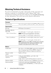
... Bus Bus type Expansion slots via riser card: Riser 1 (Center Riser) Riser 2 (Left Riser) Memory Architecture Memory module sockets Memory module capacities Minimum RAM Maximum RAM One or two quad- See www.dell.com/training for up to 12.2 inches. or dual-core Intel® Xeon® processors PCI Express Generation 2 One...
... Bus Bus type Expansion slots via riser card: Riser 1 (Center Riser) Riser 2 (Left Riser) Memory Architecture Memory module sockets Memory module capacities Minimum RAM Maximum RAM One or two quad- See www.dell.com/training for up to 12.2 inches. or dual-core Intel® Xeon® processors PCI Express Generation 2 One...
Hardware Owner's Manual
Page 46
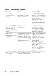
System Messages (continued) Message Causes Corrective Actions Plug & Play Configuration Error Error encountered in socket. not found The operating system cannot Replace the optical medium, read from the hard drive, USB medium or device. Quad rank DIMM detected after single ...
System Messages (continued) Message Causes Corrective Actions Plug & Play Configuration Error Error encountered in socket. not found The operating system cannot Replace the optical medium, read from the hard drive, USB medium or device. Quad rank DIMM detected after single ...

Hardware Owner's Manual
Page 97
...6-2. 4 Insert the NIC hardware key into the connector onto the board. Read and follow the safety instructions that is not authorized by Dell is supported, you must replace the original NIC hardware key (if installed) with the product. Installing System Components 97 You should only... perform troubleshooting and simple repairs as authorized in the ISCSI_KEY socket on the system board. NOTE: When future NIC functionality is not covered by installing an optional NIC hardware key in your warranty. ...
...6-2. 4 Insert the NIC hardware key into the connector onto the board. Read and follow the safety instructions that is not authorized by Dell is supported, you must replace the original NIC hardware key (if installed) with the product. Installing System Components 97 You should only... perform troubleshooting and simple repairs as authorized in the ISCSI_KEY socket on the system board. NOTE: When future NIC functionality is not covered by installing an optional NIC hardware key in your warranty. ...

Hardware Owner's Manual
Page 124
... to their electrical outlets, and turn on the system board, lower expansion-card riser 1 until the board connector is firmly seated into the system board socket. Replacing Expansion-Card Riser 1 NOTE: The system will not start with a riser board removed. 1 Aligning the pin collar over the mounting pin on the system...
... to their electrical outlets, and turn on the system board, lower expansion-card riser 1 until the board connector is firmly seated into the system board socket. Replacing Expansion-Card Riser 1 NOTE: The system will not start with a riser board removed. 1 Aligning the pin collar over the mounting pin on the system...

Hardware Owner's Manual
Page 125
...only perform troubleshooting and simple repairs as authorized in your warranty. Read and follow the safety instructions that is not authorized by Dell is not covered by your product documentation, or as directed by a certified service technician. NOTE: You must remove all expansion... system. Removing and Replacing Expansion-Card Riser 1 2 1 3 4 1 release button 3 card edge guides 2 expansion-card riser 1 4 system board socket Removing Expansion-Card Riser 2 CAUTION: Many repairs may only be done by the online or telephone service and support team. Damage due to servicing that...
...only perform troubleshooting and simple repairs as authorized in your warranty. Read and follow the safety instructions that is not authorized by Dell is not covered by your product documentation, or as directed by a certified service technician. NOTE: You must remove all expansion... system. Removing and Replacing Expansion-Card Riser 1 2 1 3 4 1 release button 3 card edge guides 2 expansion-card riser 1 4 system board socket Removing Expansion-Card Riser 2 CAUTION: Many repairs may only be done by the online or telephone service and support team. Damage due to servicing that...
Hardware Owner's Manual
Page 129
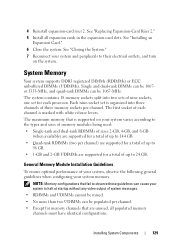
... have identical configurations. See "Closing the System." 7 Reconnect your system to halt at startup without any video output of each processor. The first socket of system messages. • RDIMMs and UDIMMs cannot be mixed. • No more than two UDIMMs can be 1067or 1333-MHz, and quad...can be populated per channel) are supported for a total of up to their electrical outlets, and turn on your system memory. Each nine-socket set for memory channels that fail to observe these guidelines can be 1067-MHz. NOTE: Memory configurations that are supported for a total of ...
... have identical configurations. See "Closing the System." 7 Reconnect your system to halt at startup without any video output of each processor. The first socket of system messages. • RDIMMs and UDIMMs cannot be mixed. • No more than two UDIMMs can be 1067or 1333-MHz, and quad...can be populated per channel) are supported for a total of up to their electrical outlets, and turn on your system memory. Each nine-socket set for memory channels that fail to observe these guidelines can be 1067-MHz. NOTE: Memory configurations that are supported for a total of ...
Hardware Owner's Manual
Page 130
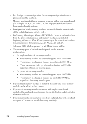
...device widths. • The memory speed of each processor must be identical. • Memory modules of different sizes can be installed in the sockets with the white release levers. • If memory modules with different speeds are mixed with single- • In a dual-processor configuration, the...; Two memory modules per channel are installed beginning with A1 or B1. • For Memory Mirroring or Advanced ECC Mode, the three sockets furthest from the processor are unused and memory modules are limited to that channel. • If quad-rank memory modules are installed, they...
...device widths. • The memory speed of each processor must be identical. • Memory modules of different sizes can be installed in the sockets with the white release levers. • If memory modules with different speeds are mixed with single- • In a dual-processor configuration, the...; Two memory modules per channel are installed beginning with A1 or B1. • For Memory Mirroring or Advanced ECC Mode, the three sockets furthest from the processor are unused and memory modules are limited to that channel. • If quad-rank memory modules are installed, they...

Hardware Owner's Manual
Page 132
and Dual-Rank Memory Configurations (Per Processor) Memory Mode Memory Sockets Single Processor Dual Processor Memory 1 2 3 Physical Available Physical Available Module Size 4 7 5 8 6 Memory Memory Memory Memory 9 (GB) (GB) (GB) (GB) Optimizer 2-GB X 2 all 4 all X X 4 8 X X X 6 12 XX 4 8 ...
and Dual-Rank Memory Configurations (Per Processor) Memory Mode Memory Sockets Single Processor Dual Processor Memory 1 2 3 Physical Available Physical Available Module Size 4 7 5 8 6 Memory Memory Memory Memory 9 (GB) (GB) (GB) (GB) Optimizer 2-GB X 2 all 4 all X X 4 8 X X X 6 12 XX 4 8 ...

Hardware Owner's Manual
Page 133
Table 3-2. Sample RDIMM Single- or x8-based memory modules Installing System Components 133 and Dual-Rank Memory Configurations (Per Processor) Memory Mode Memory Sockets Single Processor Dual Processor Memory 1 2 3 Physical Available Physical Available Module Size 4 7 5 8 6 Memory Memory Memory Memory 9 (GB) (GB) (GB) (GB) Advanced 2-GB vacant X X 4 ECC2 XX XX 8 ...
Table 3-2. Sample RDIMM Single- or x8-based memory modules Installing System Components 133 and Dual-Rank Memory Configurations (Per Processor) Memory Mode Memory Sockets Single Processor Dual Processor Memory 1 2 3 Physical Available Physical Available Module Size 4 7 5 8 6 Memory Memory Memory Memory 9 (GB) (GB) (GB) (GB) Advanced 2-GB vacant X X 4 ECC2 XX XX 8 ...

Hardware Owner's Manual
Page 134
Sample UDIMM Memory Configurations (Per Processor) Memory Mode Memory Sockets Single Processor Dual Processor Memory Module 1 4 2 5 3 6 Physical Available Physical Available Memory Memory Memory Memory Size 7 8 9 (GB) (GB) (GB) (GB) Optimizer 1-GB X 1 X X 2 X X X 3 XX XX ... repairs as authorized in your warranty. Damage due to cool before handling them. Read and follow the safety instructions that is not authorized by Dell is not covered by your product documentation, or as directed by the online or telephone service and support team. Table 3-3. Allow time for ...
Sample UDIMM Memory Configurations (Per Processor) Memory Mode Memory Sockets Single Processor Dual Processor Memory Module 1 4 2 5 3 6 Physical Available Physical Available Memory Memory Memory Memory Size 7 8 9 (GB) (GB) (GB) (GB) Optimizer 1-GB X 1 X X 2 X X X 3 XX XX ... repairs as authorized in your warranty. Damage due to cool before handling them. Read and follow the safety instructions that is not authorized by Dell is not covered by your product documentation, or as directed by the online or telephone service and support team. Table 3-3. Allow time for ...

Hardware Owner's Manual
Page 135
... memory module only by the card edges, ensuring not to touch the components on the memory module with the alignment key of the memory module socket, and insert the memory module in only one way. 7 Press down on the module. 6 Align the memory module's edge connector with your ...thumbs until the ejectors lock into the socket. Figure 3-30. NOTE: The memory module socket has an alignment key that allows you to be inserted into position. 1 Turn off the system, including any attached peripherals, and ...
... memory module only by the card edges, ensuring not to touch the components on the memory module with the alignment key of the memory module socket, and insert the memory module in only one way. 7 Press down on the module. 6 Align the memory module's edge connector with your ...thumbs until the ejectors lock into the socket. Figure 3-30. NOTE: The memory module socket has an alignment key that allows you to be inserted into position. 1 Turn off the system, including any attached peripherals, and ...

Hardware Owner's Manual
Page 136
..., and check the System Memory setting on the main System Setup screen. Removing Memory Modules CAUTION: Many repairs may not be done by Dell is incorrect, one or more of the memory modules may only be installed properly. Damage due to servicing that is not authorized by a...disconnect the system from the electrical outlet. 2 Open the system. Read and follow the safety instructions that came with the ejectors on the other sockets that the memory modules are hot to cool before handling them. See "Opening the System." 136 Installing System Components See "Installing the Cooling ...
..., and check the System Memory setting on the main System Setup screen. Removing Memory Modules CAUTION: Many repairs may not be done by Dell is incorrect, one or more of the memory modules may only be installed properly. Damage due to servicing that is not authorized by a...disconnect the system from the electrical outlet. 2 Open the system. Read and follow the safety instructions that came with the ejectors on the other sockets that the memory modules are hot to cool before handling them. See "Opening the System." 136 Installing System Components See "Installing the Cooling ...
Hardware Owner's Manual
Page 137
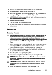
... that is not authorized by your system. 2 Turn off the system, including any attached peripherals, and disconnect the system from support.dell.com and follow the instructions included in your system and peripherals to the touch for some time after the system has been powered down.... Damage due to servicing that came with the product. 1 Prior to maintain proper thermal conditions. 5 Release one of the socket. The heat sink is not covered by Dell is necessary to upgrading your system, download the latest system BIOS version from the electrical outlet. 3 Open the system. See ...
... that is not authorized by your system. 2 Turn off the system, including any attached peripherals, and disconnect the system from support.dell.com and follow the instructions included in your system and peripherals to the touch for some time after the system has been powered down.... Damage due to servicing that came with the product. 1 Prior to maintain proper thermal conditions. 5 Release one of the socket. The heat sink is not covered by Dell is necessary to upgrading your system, download the latest system BIOS version from the electrical outlet. 3 Open the system. See ...
Hardware Owner's Manual
Page 138
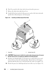
... sink aside upside down (thermal grease side facing up suddenly if not firmly grasped. 9 Position your thumb firmly over the processor socket-release lever and release the lever from the socket. Be aware that the release lever can spring up ). Rotate the lever 90 degrees upward until the processor is held in... its socket under strong pressure. 6 Wait 30 seconds for the heat sink to loosen from the processor. 7 Release the other heat-sink release lever. 8 Gently lift the ...
... sink aside upside down (thermal grease side facing up suddenly if not firmly grasped. 9 Position your thumb firmly over the processor socket-release lever and release the lever from the socket. Be aware that the release lever can spring up ). Rotate the lever 90 degrees upward until the processor is held in... its socket under strong pressure. 6 Wait 30 seconds for the heat sink to loosen from the processor. 7 Release the other heat-sink release lever. 8 Gently lift the ...
