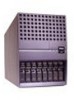
Dell PowerEdge 4400 Support Question
Dell PowerEdge 4400 Support Question
Find answers below for this question about Dell PowerEdge 4400.Need a Dell PowerEdge 4400 manual? We have 9 online manuals for this item!
Question posted by rivera30738 on March 8th, 2013
I Have A Amber Light On The Fan Icon In The Front Panel Of My Dell.
Current Answers
Answer #1: Posted by jrc1971 on March 9th, 2013 11:58 AM

Member since:
March 9th, 2013 Points: 2,200
Try these steps to ensure that you properly changed the fans:
1. Switch off the server, unplug and open the case. Check that the cable or cables that connect the fan assembly to the motherboard are correctly plugged and that no other cable may obstruct the assembly or has been unplugged when you changed it.
2. Leave the case open, plug the server and start it, looking at the fan assemby an checking that all fans work properly on the boot checking of the system performed by the BIOS. All the fans should perform a maximum voltage test. (Run at maximum speed for 2/3 seconds) if everything is correct.
On all Dell servers older an new, the amber static led indicates a power supply failure. if the two checks above have worked properly try the first logical solution: download the latest BIOS release from Dell website and save it in a pendrive; then flash the bios.
I you are unavailable to flash it from a pendrive, simply remove the battery on the motherboard with the server unplugged and wait at least for a minute until al condensers get empty, then put agin the battery in its place: this "rustical" method will turn the BIOS to its default features. (you will have to reconfigure it if it works)
If none of the above works, you will have to change the power supply of the server.
I hope this information would be useful and that you will have you server working back again.
"Two things are infinite: the universe and human stupidity; and I'm not sure about the the universe."
Albert Einstein
Related Dell PowerEdge 4400 Manual Pages


Similar Questions

hi Good Day,we are having issue with our dell R710 with error message error 1 but we look up in OMSA...

t410


