Computer Applications Guide
Page 10
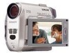
...copy pictures from a "Memory Stick" to a computer, and copying files to a "Memory Stick." • When connecting the camcorder to a computer: - If you insert the connector forcibly, it may be recognized beforehand. USB cable (supplied) - Image data is good for [Picture Package Menu] appears on ...the desktop. 10Remove the CD-ROM from the disc drive of your camcorder, or on a tape. Using the USB ...
...copy pictures from a "Memory Stick" to a computer, and copying files to a "Memory Stick." • When connecting the camcorder to a computer: - If you insert the connector forcibly, it may be recognized beforehand. USB cable (supplied) - Image data is good for [Picture Package Menu] appears on ...the desktop. 10Remove the CD-ROM from the disc drive of your camcorder, or on a tape. Using the USB ...

Computer Applications Guide
Page 15
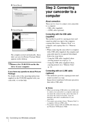
...turning off your computer has a USB keyboard and a USB mouse as shown in the following illustrations to operate the camcorder correctly. • Connect the camcorder to an available USB jack with the USB cable (supplied). To disconnect the USB cable For Windows 2000/Windows Me...a Windows computer 15 Using the i.LINK cable (optional) to DV Interface to i.LINK (IEEE1394) connector i.LINK cable (optional) ,continued Connecting to a Windows computer task tray 2 Click [Safely remove Sony Camcorder] ([Unplug or eject hardware] in Windows 2000/Windows Me. 4 Disconnect the USB cable from the...
...turning off your computer has a USB keyboard and a USB mouse as shown in the following illustrations to operate the camcorder correctly. • Connect the camcorder to an available USB jack with the USB cable (supplied). To disconnect the USB cable For Windows 2000/Windows Me...a Windows computer 15 Using the i.LINK cable (optional) to DV Interface to i.LINK (IEEE1394) connector i.LINK cable (optional) ,continued Connecting to a Windows computer task tray 2 Click [Safely remove Sony Camcorder] ([Unplug or eject hardware] in Windows 2000/Windows Me. 4 Disconnect the USB cable from the...
Computer Applications Guide
Page 25
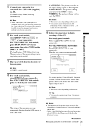
...25 Managing pictures on the tape is a blank portion of your camcorder. WRITING: The picture is being written onto the CD-R. 5 Connect your camcorder. CAPTURING: The picture recorded on a Windows computer If you insert the connector in the disc drive, then repeat steps 8 and 9. b... Note • CD-RWs cannot be damaged, and causes a malfunction of your camcorder. 6 For touch panel models, ...
...25 Managing pictures on the tape is a blank portion of your camcorder. WRITING: The picture is being written onto the CD-R. 5 Connect your camcorder. CAPTURING: The picture recorded on a Windows computer If you insert the connector in the disc drive, then repeat steps 8 and 9. b... Note • CD-RWs cannot be damaged, and causes a malfunction of your camcorder. 6 For touch panel models, ...
Computer Applications Guide
Page 28
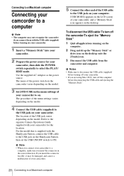
...is supplied with the Handycam Station, connect the USB cable to the USB jack on the desktop. If you insert the connector forcibly, it may not recognize the camcorder if you insert the connector in the menu settings of your camcorder to on your camcorder. Connecting to a ...Macintosh computer Connecting your camcorder to a computer b Note • The computer may ...
...is supplied with the Handycam Station, connect the USB cable to the USB jack on the desktop. If you insert the connector forcibly, it may not recognize the camcorder if you insert the connector in the menu settings of your camcorder to on your camcorder. Connecting to a ...Macintosh computer Connecting your camcorder to a computer b Note • The computer may ...
Computer Applications Guide
Page 30
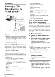
...to DVD] from a picture recorded on a tape to a DVD easily if your camcorder, then slide the POWER switch repeatedly to a DVD. Other functions Creating a DVD (Direct Access to "Click to DVD") to i.LINK (IEEE1394) connector i.LINK cable (optional) to DV Interface b Notes • Some models are ... to DVD Automatic Mode Launcher] is automatically copied and written to select the PLAY/ EDIT mode. Asia Pacific Regional http://www.css.ap.sony.com/ - Quit all applications running with "Click to create a 30 Other functions Regarding supported models, check to DVD Automatic Mode Launcher]...
...to DVD] from a picture recorded on a tape to a DVD easily if your camcorder, then slide the POWER switch repeatedly to a DVD. Other functions Creating a DVD (Direct Access to "Click to DVD") to i.LINK (IEEE1394) connector i.LINK cable (optional) to DV Interface b Notes • Some models are ... to DVD Automatic Mode Launcher] is automatically copied and written to select the PLAY/ EDIT mode. Asia Pacific Regional http://www.css.ap.sony.com/ - Quit all applications running with "Click to create a 30 Other functions Regarding supported models, check to DVD Automatic Mode Launcher]...
Computer Applications Guide
Page 31
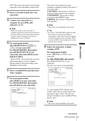
... DVD in the disc drive of your computer. "Click to DVD" starts up and the on-screen instructions appear on the LCD screen of your camcorder. CONVERTING: The picture is a recorded disc. YES NO To create another copy? b Note • The screen varies depending on the [SELECT DISC... insert the connector forcibly, it , the message [This is being written onto the DVD. The name of your computer is written. 8 Follow the steps below to the MPEG2 format. For SEL/PUSH EXEC dial models, press BURN DVD/VCD of the power switch on the camcorder varies depending ...
... DVD in the disc drive of your computer. "Click to DVD" starts up and the on-screen instructions appear on the LCD screen of your camcorder. CONVERTING: The picture is a recorded disc. YES NO To create another copy? b Note • The screen varies depending on the [SELECT DISC... insert the connector forcibly, it , the message [This is being written onto the DVD. The name of your computer is written. 8 Follow the steps below to the MPEG2 format. For SEL/PUSH EXEC dial models, press BURN DVD/VCD of the power switch on the camcorder varies depending ...
Computer Applications Guide
Page 33
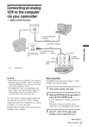
...VCR to a digital signal and transfer it to a digital device, such as the power source. The name of the power switch on the camcorder varies depending on the model. 3 Set [A/VtDV OUT] in the index of the Camera Operations Guide. • The supplied A/V cable ... the analog video unit. 2 Slide the POWER switch repeatedly to select the PLAY/EDIT mode. Digital convert function DV Interface Other functions to i.LINK (IEEE1394) connector i.LINK cable (optional) : Signal flow A/V connecting cable A/V (audio/video) (supplied) (White) jack (Red) AUDIO/VIDEO jacks (Yellow) S video plug (...
...VCR to a digital signal and transfer it to a digital device, such as the power source. The name of the power switch on the camcorder varies depending on the model. 3 Set [A/VtDV OUT] in the index of the Camera Operations Guide. • The supplied A/V cable ... the analog video unit. 2 Slide the POWER switch repeatedly to select the PLAY/EDIT mode. Digital convert function DV Interface Other functions to i.LINK (IEEE1394) connector i.LINK cable (optional) : Signal flow A/V connecting cable A/V (audio/video) (supplied) (White) jack (Red) AUDIO/VIDEO jacks (Yellow) S video plug (...

Computer Applications Guide
Page 34
... a computer. • You can use a USB cable instead of an i.LINK cable (optional) to transfer pictures to the separate Camera Operations Guide supplied with your camcorder. • When you insert the connector in the correct direction. After capturing images and sound Stop capturing procedures on your computer. For details, refer to a computer.
... a computer. • You can use a USB cable instead of an i.LINK cable (optional) to transfer pictures to the separate Camera Operations Guide supplied with your camcorder. • When you insert the connector in the correct direction. After capturing images and sound Stop capturing procedures on your computer. For details, refer to a computer.
Camera Operations Guide
Page 4
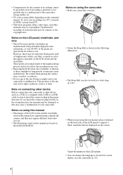
... manufactured using the touch panel, place your hand on the back side of the LCD panel to insert the connector plug in the wrong direction, the terminal may cause a malfunction of your camcorder. These points are using extremely high-precision technology, so over 99.99% of the pixels are based on... the model DCR-HC40. Doing so might cause your camcorder correctly. • Fasten the Strap Belt as a VCR or a computer with a USB or i.LINK cable, be sure to support it. Be careful when ...
... manufactured using the touch panel, place your hand on the back side of the LCD panel to insert the connector plug in the wrong direction, the terminal may cause a malfunction of your camcorder. These points are using extremely high-precision technology, so over 99.99% of the pixels are based on... the model DCR-HC40. Doing so might cause your camcorder correctly. • Fasten the Strap Belt as a VCR or a computer with a USB or i.LINK cable, be sure to support it. Be careful when ...

Camera Operations Guide
Page 114
Symptom Cause and/or Corrective Actions The Cassette Memory indicator does cClean the gold-plated connector of the cassette. (p. 126) not appear while using a cassette with Cassette Memory. (p. 125) cErase unnecessary titles when the Cassette Memory is full. (p. 81) ...also set [DEMO MODE] to [OFF] on the menu. (p. 78) An unknown indicator appears on the cRefer to [ON] on the screen. • The camcorder is in the viewfinder when the LCD panel is not cExtend the viewfinder. (p. 21) clear. The remaining tape indicator is not a malfunction. 114 Troubleshooting screen.
Symptom Cause and/or Corrective Actions The Cassette Memory indicator does cClean the gold-plated connector of the cassette. (p. 126) not appear while using a cassette with Cassette Memory. (p. 125) cErase unnecessary titles when the Cassette Memory is full. (p. 81) ...also set [DEMO MODE] to [OFF] on the menu. (p. 78) An unknown indicator appears on the cRefer to [ON] on the screen. • The camcorder is in the viewfinder when the LCD panel is not cExtend the viewfinder. (p. 21) clear. The remaining tape indicator is not a malfunction. 114 Troubleshooting screen.
Camera Operations Guide
Page 126
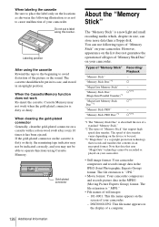
.... Labeling position After using Cassette Memory. When cleaning the gold-plated connector Generally, clean the gold-plated connector on the display of a computer. However, appearance on the list does not guarantee the operation of all types of "Memory Stick Duo" on your camcorder. a*2*3 *1 The "Memory Stick Duo" is ".MPG." • File names of...
.... Labeling position After using Cassette Memory. When cleaning the gold-plated connector Generally, clean the gold-plated connector on the display of a computer. However, appearance on the list does not guarantee the operation of all types of "Memory Stick Duo" on your camcorder. a*2*3 *1 The "Memory Stick Duo" is ".MPG." • File names of...
Camera Operations Guide
Page 135
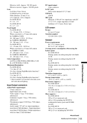
... g (1 lb) including the NP-FP50 rechargeable battery pack and DVM60 cassette. For DCR-HC30: 380 g (13 oz) main unit only 440 g (15 oz) including the NP-FP50 ,continued Additional Information 135 Additional Information Input/Output connectors Audio/Video input/output 10-pin connector Input/output auto switch Video signal: 1 Vp-p, 75 Ω (ohms), unbalanced...
... g (1 lb) including the NP-FP50 rechargeable battery pack and DVM60 cassette. For DCR-HC30: 380 g (13 oz) main unit only 440 g (15 oz) including the NP-FP50 ,continued Additional Information 135 Additional Information Input/Output connectors Audio/Video input/output 10-pin connector Input/output auto switch Video signal: 1 Vp-p, 75 Ω (ohms), unbalanced...


