Setup and Quick Reference Guide
Page 4
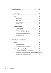
3 Specifications 23 4 Troubleshooting 35 Tools 35 Power Lights 35 Beep Codes 35 Error Messages 37 Dell Diagnostics 42 Solving Problems 44 Power Problems 45 Memory Problems 46 Lockups and Software Problems 47 Dell™ Technical Update Service 49 Dell Support Utility 49 5 Reinstalling Software 51 Drivers 51 Identifying Drivers 51 Reinstalling Drivers and Utilities 51 Restoring Your Operating System 54 Using Microsoft Windows System Restore . . . . . 54 Using Dell™ PC Restore and Dell Factory Image Restore 56 Using the Operating System Media 59 4 Contents
3 Specifications 23 4 Troubleshooting 35 Tools 35 Power Lights 35 Beep Codes 35 Error Messages 37 Dell Diagnostics 42 Solving Problems 44 Power Problems 45 Memory Problems 46 Lockups and Software Problems 47 Dell™ Technical Update Service 49 Dell Support Utility 49 5 Reinstalling Software 51 Drivers 51 Identifying Drivers 51 Reinstalling Drivers and Utilities 51 Restoring Your Operating System 54 Using Microsoft Windows System Restore . . . . . 54 Using Dell™ PC Restore and Dell Factory Image Restore 56 Using the Operating System Media 59 4 Contents

Setup and Quick Reference Guide
Page 24
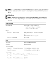
...xD-Picture Card • Hi Speed-SD • Hi Density-SD Memory Memory module connector 2 DIMM slots Memory module capacity 512 MB, 1 GB, or 2 GB Memory type DDR2 667 MHz Minimum memory 512 MB Maximum memory 4 GB NOTE: In order to take advantage of the dual-channel... bandwidth capability, both USB- NOTE: The available memory displayed does not reflect the complete maximum memory installed because some memory is reserved for system files. 24 Specifications ExpressCard (continued) ExpressCard connector Cards supported ExpressCard connector...
...xD-Picture Card • Hi Speed-SD • Hi Density-SD Memory Memory module connector 2 DIMM slots Memory module capacity 512 MB, 1 GB, or 2 GB Memory type DDR2 667 MHz Minimum memory 512 MB Maximum memory 4 GB NOTE: In order to take advantage of the dual-channel... bandwidth capability, both USB- NOTE: The available memory displayed does not reflect the complete maximum memory installed because some memory is reserved for system files. 24 Specifications ExpressCard (continued) ExpressCard connector Cards supported ExpressCard connector...

Setup and Quick Reference Guide
Page 26
... Speaker Internal speaker amplifier Volume controls Vostro 1310 and 1510 discrete: • NVIDIA GeForce 8400M GS, 64 bit Vostro 1710 discrete: • NVIDIA GeForce 8600M GS, 128 bit Vostro 1310, 1510, and 1710 integrated: • up to 256 MB of shared memory Vostro 1310 discrete: • 128 MB Vostro 1510 discrete: • 256 MB Vostro 1710 discrete: • 256 MB...
... Speaker Internal speaker amplifier Volume controls Vostro 1310 and 1510 discrete: • NVIDIA GeForce 8400M GS, 64 bit Vostro 1710 discrete: • NVIDIA GeForce 8600M GS, 128 bit Vostro 1310, 1510, and 1710 integrated: • up to 256 MB of shared memory Vostro 1310 discrete: • 128 MB Vostro 1510 discrete: • 256 MB Vostro 1710 discrete: • 256 MB...
Setup and Quick Reference Guide
Page 35
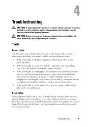
If the power light is blinking amber, the computer is receiving electrical power, a device such as a memory module or graphics card might emit a series of beeps during start-up if the monitor cannot display errors or problems. This series of beeps, called a ...
If the power light is blinking amber, the computer is receiving electrical power, a device such as a memory module or graphics card might emit a series of beeps during start-up if the monitor cannot display errors or problems. This series of beeps, called a ...

Setup and Quick Reference Guide
Page 36
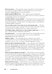
... with your computer (see your computer beeps during start-up: 1 Write down the beep code. 2 Run the Dell Diagnostics to identify a more serious cause (see "Dell Diagnostics" on page 42). Possible motherboard failure. 2 No memory modules 1 If you are installing are detected installed, remove the modules, reinstall one module (see your Service Manual...
... with your computer (see your computer beeps during start-up: 1 Write down the beep code. 2 Run the Dell Diagnostics to identify a more serious cause (see "Dell Diagnostics" on page 42). Possible motherboard failure. 2 No memory modules 1 If you are installing are detected installed, remove the modules, reinstall one module (see your Service Manual...

Setup and Quick Reference Guide
Page 37
.... DATA ERROR - The hard drive cannot read the data. DI S K C : F A I A R Y DEVICE FAILURE - battery failure or 2 If the problem persists, contact Dell. See your Service Manual failure. AU X I L I L E D INITIALIZATION - Reinstall the memory modules and, if necessary, replace them. Run the hard drive tests in the system setup program. Code Description (repetitive short beeps...
.... DATA ERROR - The hard drive cannot read the data. DI S K C : F A I A R Y DEVICE FAILURE - battery failure or 2 If the problem persists, contact Dell. See your Service Manual failure. AU X I L I L E D INITIALIZATION - Reinstall the memory modules and, if necessary, replace them. Run the hard drive tests in the system setup program. Code Description (repetitive short beeps...
Setup and Quick Reference Guide
Page 38
.... H A R D - Run the Hard Disk Drive tests in the computer. See your Service Manual at support.dell.com for example, Printer out of memory recorded in nonvolatile memory (NVRAM) does not match the memory installed in the Dell Diagnostics (see "Dell Diagnostics" on page 42). The message is too large to carry out the command. Shut down...
.... H A R D - Run the Hard Disk Drive tests in the computer. See your Service Manual at support.dell.com for example, Printer out of memory recorded in nonvolatile memory (NVRAM) does not match the memory installed in the Dell Diagnostics (see "Dell Diagnostics" on page 42). The message is too large to carry out the command. Shut down...
Setup and Quick Reference Guide
Page 39
...computer, and avoid touching the keyboard or the mouse during the boot routine. Run the Keyboard Controller test in the Dell Diagnostics (see "Dell Diagnostics" on page 42). Run the Stuck Key test in the system setup program. INVALID CONFIGURATION INFORMATION-PLEASE RUN ... another drive. Then, shut down the computer, reinstall the hard drive, and restart the computer. The operating system is trying to boot to occur after a memory module is most likely to nonbootable media, such as a floppy disk or CD. K E Y B O A R D C L O C K L I N E F A I L U R E - If the problem ...
...computer, and avoid touching the keyboard or the mouse during the boot routine. Run the Keyboard Controller test in the Dell Diagnostics (see "Dell Diagnostics" on page 42). Run the Stuck Key test in the system setup program. INVALID CONFIGURATION INFORMATION-PLEASE RUN ... another drive. Then, shut down the computer, reinstall the hard drive, and restart the computer. The operating system is trying to boot to occur after a memory module is most likely to nonbootable media, such as a floppy disk or CD. K E Y B O A R D C L O C K L I N E F A I L U R E - If the problem ...
Setup and Quick Reference Guide
Page 40
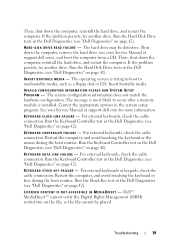
... the hard drive is installed, properly seated, and partitioned as a boot device. Contact Dell (see the software documentation. MEMORY DOUBLE WORD LOGIC FAILURE AT ADDRESS, READ VALUE EXPECTING VALUE - MEMORY ADDRESS LINE FAILURE AT ADDRESS, READ VALUE EXPECTING VALUE - The software you want to ... too many programs open the program that the drive is your Service Manual at support.dell.com for more information. Reinstall the memory modules and, if necessary, replace them. A memory module may be faulty or improperly seated. See your boot device, ensure that you ...
... the hard drive is installed, properly seated, and partitioned as a boot device. Contact Dell (see the software documentation. MEMORY DOUBLE WORD LOGIC FAILURE AT ADDRESS, READ VALUE EXPECTING VALUE - MEMORY ADDRESS LINE FAILURE AT ADDRESS, READ VALUE EXPECTING VALUE - The software you want to ... too many programs open the program that the drive is your Service Manual at support.dell.com for more information. Reinstall the memory modules and, if necessary, replace them. A memory module may be faulty or improperly seated. See your boot device, ensure that you ...

Setup and Quick Reference Guide
Page 42
... to an electrical outlet; OF -D A Y CLOCK STOPPED - T H E D E V I C E I C A L L Y L O W - WA R N I N G : B A T T E R Y I S C R I T I S N O T R E A D Y - Replace the battery, or connect the computer to charge the battery. U N E X P E C T E D I N T E R R U P T I N P R O T E C T E D M O D E - Run the System Memory tests and the Keyboard Controller test in the Dell Diagnostics (see "Lockups and Software Problems" on page 42). The time or date stored in Lockups and Software Problems (see...
... to an electrical outlet; OF -D A Y CLOCK STOPPED - T H E D E V I C E I C A L L Y L O W - WA R N I N G : B A T T E R Y I S C R I T I S N O T R E A D Y - Replace the battery, or connect the computer to charge the battery. U N E X P E C T E D I N T E R R U P T I N P R O T E C T E D M O D E - Run the System Memory tests and the Keyboard Controller test in the Dell Diagnostics (see "Lockups and Software Problems" on page 42). The time or date stored in Lockups and Software Problems (see...
Setup and Quick Reference Guide
Page 45
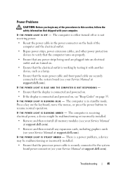
.... • Ensure that the display is connected and powered on. • If the display is connected and powered on, see your Service Manual at support.dell.com). I F T H E P O W E R L I G H T I S B L I N K I N G A M B E R - Troubleshooting 45 The computer is in this section, follow the safety information ...a power problem, a device may be malfunctioning or incorrectly installed. • Remove and then reinstall all memory modules (see your Service Manual at support.dell.com). • Remove and then reinstall any power strips being used are plugged into an electrical outlet ...
.... • Ensure that the display is connected and powered on. • If the display is connected and powered on, see your Service Manual at support.dell.com). I F T H E P O W E R L I G H T I S B L I N K I N G A M B E R - Troubleshooting 45 The computer is in this section, follow the safety information ...a power problem, a device may be malfunctioning or incorrectly installed. • Remove and then reinstall all memory modules (see your Service Manual at support.dell.com). • Remove and then reinstall any power strips being used are plugged into an electrical outlet ...
Setup and Quick Reference Guide
Page 46
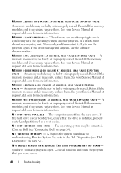
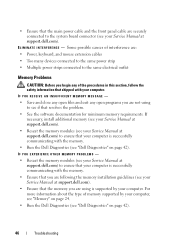
... the procedures in this section, follow the safety information that shipped with the memory. • Run the Dell Diagnostics (see "Dell Diagnostics" on page 42). 46 Troubleshooting IF YOU EXPERIENCE OTHER MEMORY PROBLEMS - • Reseat the memory modules (see your Service Manual at support.dell.com) to ensure that your computer is successfully communicating with the...
... the procedures in this section, follow the safety information that shipped with the memory. • Run the Dell Diagnostics (see "Dell Diagnostics" on page 42). 46 Troubleshooting IF YOU EXPERIENCE OTHER MEMORY PROBLEMS - • Reseat the memory modules (see your Service Manual at support.dell.com) to ensure that your computer is successfully communicating with the...
Setup and Quick Reference Guide
Page 71
... identifying, 51 reinstalling, 51 Drivers and Utilities media, 52 Dell Diagnostics, 42 E ergonomics information, 62 error messages, 37 beep codes, 35 F Factory Image Restore, 56, 58 Files and Settings Transfer Wizard, 19 H hardware beep codes, 35 Dell Diagnostics, 42 I Internet connection about, 17 options, 17 setting up, 18 M memory troubleshooting, 46 Index 71
... identifying, 51 reinstalling, 51 Drivers and Utilities media, 52 Dell Diagnostics, 42 E ergonomics information, 62 error messages, 37 beep codes, 35 F Factory Image Restore, 56, 58 Files and Settings Transfer Wizard, 19 H hardware beep codes, 35 Dell Diagnostics, 42 I Internet connection about, 17 options, 17 setting up, 18 M memory troubleshooting, 46 Index 71

Setup and Quick Reference Guide
Page 72
..., 62 setup, 15 software reinstalling, 51 troubleshooting, 48 specifications, 23 Starting the Dell Diagnostics From the Drivers and Utilities Media, 44 Starting the Dell Diagnostics From Your Hard Drive, 43 support contacting Dell, 69 System Restore, 54 T Technical Update Service, 49 transferring information to a new... computer, 19 troubleshooting, 35 beep codes, 35 blue screen, 48 computer stops responding, 47 Dell Diagnostics, 42 error messages, 37 lockups, 47 memory, 46 power, 45 power light conditions, 45 power lights, 35 programs and Windows compatibility, 48 restore to previous...
..., 62 setup, 15 software reinstalling, 51 troubleshooting, 48 specifications, 23 Starting the Dell Diagnostics From the Drivers and Utilities Media, 44 Starting the Dell Diagnostics From Your Hard Drive, 43 support contacting Dell, 69 System Restore, 54 T Technical Update Service, 49 transferring information to a new... computer, 19 troubleshooting, 35 beep codes, 35 blue screen, 48 computer stops responding, 47 Dell Diagnostics, 42 error messages, 37 lockups, 47 memory, 46 power, 45 power light conditions, 45 power lights, 35 programs and Windows compatibility, 48 restore to previous...
Setup and Features Information Tech Sheet
Page 8
...may vary by region. For more information regarding the configuration of shared memory Vostro 1310 discrete 128 MB Vostro 1510, 1710, and 2510 discrete 256 MB System Information Processor type Chipset Vostro 1310, 1510, and 1710 Vostro 2510 integrated Vostro 1310, 1510, 1710 and 2510: Intel® Core™ 2 Duo (1.4-2.6 ... on system board Data bus integrated video Video controller Vostro 1310, 1510, and 2510 discrete NVIDIA GeForce 8400M GS, 64 bit Vostro 1710 discrete NVIDIA GeForce 8600M GS, 128 bit Video memory Vostro 1310, 1510, and 1710 integrated up to 256 MB of your...
...may vary by region. For more information regarding the configuration of shared memory Vostro 1310 discrete 128 MB Vostro 1510, 1710, and 2510 discrete 256 MB System Information Processor type Chipset Vostro 1310, 1510, and 1710 Vostro 2510 integrated Vostro 1310, 1510, 1710 and 2510: Intel® Core™ 2 Duo (1.4-2.6 ... on system board Data bus integrated video Video controller Vostro 1310, 1510, and 2510 discrete NVIDIA GeForce 8400M GS, 64 bit Vostro 1710 discrete NVIDIA GeForce 8600M GS, 128 bit Video memory Vostro 1310, 1510, and 1710 integrated up to 256 MB of your...
Service Manual
Page 1
... loss of Microsoft Corporation in this document to avoid the problem. Bluetooth is a registered trademark of your computer. Dell™ Vostro™ 1510 Service Manual Troubleshooting Before Working on Your Computer Hard Drive Wireless Local Area Network (WLAN) Card Fan Processor Thermal...-Cooling Assembly Processor Module Memory Hinge Cover Keyboard Power Button and Multimedia Button Pads Display Palm Rest Fingerprint Reader ...
... loss of Microsoft Corporation in this document to avoid the problem. Bluetooth is a registered trademark of your computer. Dell™ Vostro™ 1510 Service Manual Troubleshooting Before Working on Your Computer Hard Drive Wireless Local Area Network (WLAN) Card Fan Processor Thermal...-Cooling Assembly Processor Module Memory Hinge Cover Keyboard Power Button and Multimedia Button Pads Display Palm Rest Fingerprint Reader ...
Service Manual
Page 2
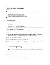
Back to Contents Page Before Working on Your Computer Dell™ Vostro™ 1510 Service Manual Recommended Tools What You Need to Know for Your Safety This document provides procedures for removing and installing the components in your own ... repairs may only be done by the online or telephone service and support team. You should only perform troubleshooting and simple repairs as authorized in -1 memory card reader. l In Windows XP, click Start® Shutdown® Shutdown. NOTE: Ensure that the computer is off your computer and certain components may require...
Back to Contents Page Before Working on Your Computer Dell™ Vostro™ 1510 Service Manual Recommended Tools What You Need to Know for Your Safety This document provides procedures for removing and installing the components in your own ... repairs may only be done by the online or telephone service and support team. You should only perform troubleshooting and simple repairs as authorized in -1 memory card reader. l In Windows XP, click Start® Shutdown® Shutdown. NOTE: Ensure that the computer is off your computer and certain components may require...
Service Manual
Page 10
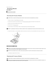
...is perpendicular to the cam stop. 1 ZIF-socket cam screw 2 ZIF socket NOTICE: To ensure maximum cooling for an illustration of the memory cover.) 3. Press and hold the screwdriver so that it comes to the processor when turning the cam screw. 6. NOTICE: Do not... that secure the memory cover. (See Removing a Memory Module for the processor, do not touch the heat transfer areas on the processor module. 7. Remove the processor thermal-cooling assembly (see Removing the Fan). 5. Back to Contents Page Processor Module Dell™ Vostro™ 1510 Service Manual Removing the...
...is perpendicular to the cam stop. 1 ZIF-socket cam screw 2 ZIF socket NOTICE: To ensure maximum cooling for an illustration of the memory cover.) 3. Press and hold the screwdriver so that it comes to the processor when turning the cam screw. 6. NOTICE: Do not... that secure the memory cover. (See Removing a Memory Module for the processor, do not touch the heat transfer areas on the processor module. 7. Remove the processor thermal-cooling assembly (see Removing the Fan). 5. Back to Contents Page Processor Module Dell™ Vostro™ 1510 Service Manual Removing the...
Service Manual
Page 11
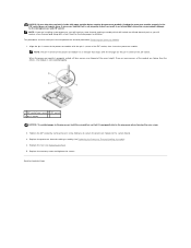
... the processor module has a triangle that aligns with the triangle on the pin-1 corner of the ZIF socket, then insert the processor module. Replace the memory cover and tighten the screws. NOTICE: Ensure that the cam lock is in the ZIF socket does not require force. This procedure assumes that you...
... the processor module has a triangle that aligns with the triangle on the pin-1 corner of the ZIF socket, then insert the processor module. Replace the memory cover and tighten the screws. NOTICE: Ensure that the cam lock is in the ZIF socket does not require force. This procedure assumes that you...
Service Manual
Page 12
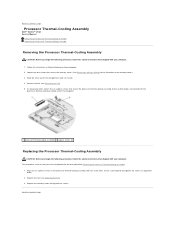
... on the processor thermal-cooling assembly with the screw holes on Your Computer. 2. Replace the memory cover and tighten the screws. Back to Contents Page Back to Contents Page Processor Thermal-Cooling Assembly Dell™ Vostro™ 1510 Service Manual Removing the Processor Thermal-Cooling Assembly Replacing the Processor Thermal-Cooling Assembly Removing the...
... on the processor thermal-cooling assembly with the screw holes on Your Computer. 2. Replace the memory cover and tighten the screws. Back to Contents Page Back to Contents Page Processor Thermal-Cooling Assembly Dell™ Vostro™ 1510 Service Manual Removing the Processor Thermal-Cooling Assembly Replacing the Processor Thermal-Cooling Assembly Removing the...


