Setup and Quick Reference Guide
Page 23
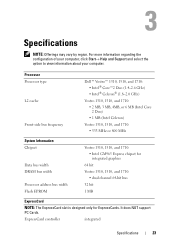
... about your computer. ExpressCard controller integrated Specifications 23 Processor Processor type L2 cache Front-side bus frequency Dell™ Vostro™ 1310, 1510, and 1710: • Intel® Core™2 Duo (1.4-2.6 GHz) • Intel® Celeron® (1.8-2.0 GHz) Vostro 1310, 1510, and 1710: • 2 MB, 3 MB... MHz System Information Chipset Data bus width DRAM bus width Processor address bus width Flash EPROM Vostro 1310, 1510, and 1710: • Intel GM965 Express chipset for integrated graphics 64 bit Vostro 1310, 1510, and 1710: • dual channel 64-bit bus ...
... about your computer. ExpressCard controller integrated Specifications 23 Processor Processor type L2 cache Front-side bus frequency Dell™ Vostro™ 1310, 1510, and 1710: • Intel® Core™2 Duo (1.4-2.6 GHz) • Intel® Celeron® (1.8-2.0 GHz) Vostro 1310, 1510, and 1710: • 2 MB, 3 MB... MHz System Information Chipset Data bus width DRAM bus width Processor address bus width Flash EPROM Vostro 1310, 1510, and 1710: • Intel GM965 Express chipset for integrated graphics 64 bit Vostro 1310, 1510, and 1710: • dual channel 64-bit bus ...
Setup and Quick Reference Guide
Page 45
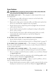
IF THE POWER LIGHT IS BLUE AND THE COMPUTER IS NOT RESPONDING - • Ensure that the processor power cable is connected and powered on, see "Beep Codes" on page 35. There is a power problem, a device may... display is connected and powered on. • If the display is securely connected to the system board power connector (see your Service Manual at support.dell.com). I F T H E P O W E R L I G H T I N G B L U E - IF T H E POWER LIGHT IS OFF - I F T H E P O W E R L I G H T I S B L I N K I S S T E A D Y A M B E R - The computer is not receiving power. • Reseat the power cable ...
IF THE POWER LIGHT IS BLUE AND THE COMPUTER IS NOT RESPONDING - • Ensure that the processor power cable is connected and powered on, see "Beep Codes" on page 35. There is a power problem, a device may... display is connected and powered on. • If the display is securely connected to the system board power connector (see your Service Manual at support.dell.com). I F T H E P O W E R L I G H T I N G B L U E - IF T H E POWER LIGHT IS OFF - I F T H E P O W E R L I G H T I S B L I N K I S S T E A D Y A M B E R - The computer is not receiving power. • Reseat the power cable ...
Setup and Features Information Tech Sheet
Page 8
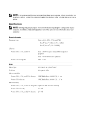
... 1710 integrated up to a docking device or other external device, such as a printer. System Information Processor type Chipset Vostro 1310, 1510, and 1710 Vostro 2510 integrated Vostro 1310, 1510, 1710 and 2510: Intel® Core™ 2 Duo (1.4-2.6 GHz) Intel Celeron® (1.8-2.0 GHz) Intel GM965 Express chipset for integrated graphics Intel PM965 for discrete graphics ... option to view information about your computer at least once before you install any cards or connect the computer to 256 MB of shared memory Vostro 1310 discrete 128 MB Vostro 1510, 1710, and 2510 discrete 256 MB
... 1710 integrated up to a docking device or other external device, such as a printer. System Information Processor type Chipset Vostro 1310, 1510, and 1710 Vostro 2510 integrated Vostro 1310, 1510, 1710 and 2510: Intel® Core™ 2 Duo (1.4-2.6 GHz) Intel Celeron® (1.8-2.0 GHz) Intel GM965 Express chipset for integrated graphics Intel PM965 for discrete graphics ... option to view information about your computer at least once before you install any cards or connect the computer to 256 MB of shared memory Vostro 1310 discrete 128 MB Vostro 1510, 1710, and 2510 discrete 256 MB
Service Manual
Page 1
...A01 Microsoft, Windows, Windows Vista, and the Windows start button logo are trademarks of Dell Inc.; disclaims any references in this text: Dell, the DELL logo, and Vostro are either potential damage to hardware or loss of data and tells you how to ...indicates potential for property damage, personal injury, or death. Dell™ Vostro™ 1510 Service Manual Troubleshooting Before Working on Your Computer Hard Drive Wireless Local Area Network (WLAN) Card Fan Processor Thermal-Cooling Assembly Processor Module Memory Hinge Cover Keyboard Power Button and Multimedia Button ...
...A01 Microsoft, Windows, Windows Vista, and the Windows start button logo are trademarks of Dell Inc.; disclaims any references in this text: Dell, the DELL logo, and Vostro are either potential damage to hardware or loss of data and tells you how to ...indicates potential for property damage, personal injury, or death. Dell™ Vostro™ 1510 Service Manual Troubleshooting Before Working on Your Computer Hard Drive Wireless Local Area Network (WLAN) Card Fan Processor Thermal-Cooling Assembly Processor Module Memory Hinge Cover Keyboard Power Button and Multimedia Button ...
Service Manual
Page 2
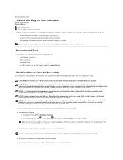
...then unplug it from potential damage and to help protect your computer. Back to Contents Page Before Working on Your Computer Dell™ Vostro™ 1510 Service Manual Recommended Tools What You Need to Know for Your Safety This document provides procedures for removing and installing the ... website at support.dell.com) What You Need to Know for 4 seconds. 3. Hold a component such as authorized in a power management mode. NOTE: The color of the computer. You should only perform troubleshooting and simple repairs as a processor by its edges, not by its metal mounting ...
...then unplug it from potential damage and to help protect your computer. Back to Contents Page Before Working on Your Computer Dell™ Vostro™ 1510 Service Manual Recommended Tools What You Need to Know for Your Safety This document provides procedures for removing and installing the ... website at support.dell.com) What You Need to Know for 4 seconds. 3. Hold a component such as authorized in a power management mode. NOTE: The color of the computer. You should only perform troubleshooting and simple repairs as a processor by its edges, not by its metal mounting ...
Service Manual
Page 10
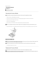
... transfer capability of the memory cover.) 3. NOTICE: To avoid damage to the processor, hold the processor down on the substrate on the processor module. 7. Back to Contents Page Processor Module Dell™ Vostro™ 1510 Service Manual Removing the Processor Module Replacing the Processor Module Removing the Processor Module CAUTION: Before you begin the following procedure, follow the safety instructions...
... transfer capability of the memory cover.) 3. NOTICE: To avoid damage to the processor, hold the processor down on the substrate on the processor module. 7. Back to Contents Page Processor Module Dell™ Vostro™ 1510 Service Manual Removing the Processor Module Replacing the Processor Module Removing the Processor Module CAUTION: Before you begin the following procedure, follow the safety instructions...
Service Manual
Page 11
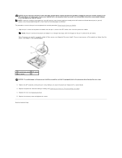
... cam screw 2 ZIF socket 3 pin-1 corner NOTICE: To avoid damage to the microprocessor and ZIF socket. Replace the fan (see Replacing the Processor Thermal-Cooling Assembly). 4. If one or more corners of the ZIF socket. Back to the system board. 3. Align the pin-1 corner of the...assumes that the cam lock is not properly seated can result in the ZIF socket does not require force. When the processor module is perpendicular to illustrate proper installation. Replace the processor thermal-cooling assembly (see Replacing the Fan). 5. Replace the memory cover and tighten the screws...
... cam screw 2 ZIF socket 3 pin-1 corner NOTICE: To avoid damage to the microprocessor and ZIF socket. Replace the fan (see Replacing the Processor Thermal-Cooling Assembly). 4. If one or more corners of the ZIF socket. Back to the system board. 3. Align the pin-1 corner of the...assumes that the cam lock is not properly seated can result in the ZIF socket does not require force. When the processor module is perpendicular to illustrate proper installation. Replace the processor thermal-cooling assembly (see Replacing the Fan). 5. Replace the memory cover and tighten the screws...
Service Manual
Page 12
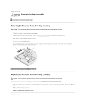
... of the compartment and set it aside. 4. Back to Contents Page Back to Contents Page Processor Thermal-Cooling Assembly Dell™ Vostro™ 1510 Service Manual Removing the Processor Thermal-Cooling Assembly Replacing the Processor Thermal-Cooling Assembly Removing the Processor Thermal-Cooling Assembly CAUTION: Before you begin the following procedure, follow the safety instructions that shipped...
... of the compartment and set it aside. 4. Back to Contents Page Back to Contents Page Processor Thermal-Cooling Assembly Dell™ Vostro™ 1510 Service Manual Removing the Processor Thermal-Cooling Assembly Replacing the Processor Thermal-Cooling Assembly Removing the Processor Thermal-Cooling Assembly CAUTION: Before you begin the following procedure, follow the safety instructions that shipped...
Service Manual
Page 52
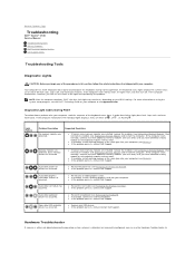
Back to Contents Page Troubleshooting Dell™ Vostro™ 1510 Service Manual Troubleshooting Tools Solving Problems Dell Technical Update Service Dell Support Utility Troubleshooting Tools Diagnostic Lights CAUTION: Before you begin any of the lights to help identify the problem. If ... detected. l If available, install working memory of the same type into your BIOS settings. l Reseat the processor (see Removing the Keyboard). l Reseat the LCD cable (see the Dell™ Technology Guide on your computer or at a time) until you can use the Hardware Troubleshooter to install...
Back to Contents Page Troubleshooting Dell™ Vostro™ 1510 Service Manual Troubleshooting Tools Solving Problems Dell Technical Update Service Dell Support Utility Troubleshooting Tools Diagnostic Lights CAUTION: Before you begin any of the lights to help identify the problem. If ... detected. l If available, install working memory of the same type into your BIOS settings. l Reseat the processor (see Removing the Keyboard). l Reseat the LCD cable (see the Dell™ Technology Guide on your computer or at a time) until you can use the Hardware Troubleshooter to install...


