
Setup and Quick Reference Guide
Page 42
... your computer. T H E D E V I C E I C A L L Y L O W - Replace the battery, or connect the computer to charge the battery. P L E A S E R U N T H E S YS T E M S E T U P P R O G R A M - When to charge the battery. TIME- The reserve battery that shipped with your computer, perform the checks in Lockups and Software Problems (see "Dell Diagnostics" on page 69). WA R N I N G : B A T T E R Y I S C R I T I S N O T R E A D Y - D A Y C L O C K L O S T P O W E R - Run the System Memory tests and the Keyboard Controller test...
... your computer. T H E D E V I C E I C A L L Y L O W - Replace the battery, or connect the computer to charge the battery. P L E A S E R U N T H E S YS T E M S E T U P P R O G R A M - When to charge the battery. TIME- The reserve battery that shipped with your computer, perform the checks in Lockups and Software Problems (see "Dell Diagnostics" on page 69). WA R N I N G : B A T T E R Y I S C R I T I S N O T R E A D Y - D A Y C L O C K L O S T P O W E R - Run the System Memory tests and the Keyboard Controller test...
Service Manual
Page 6
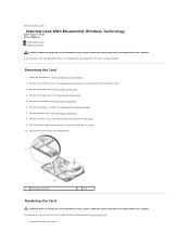
... Removing a WLAN Card). 4. Remove the WLAN card (see Removing the Keyboard). 6. Remove the display assembly (see Removing the Palm Rest). 8. This procedure assumes that you ordered a card with Bluetooth wireless technology with your computer... follow the safety instructions that shipped with your computer. Back to Contents Page Internal Card With Bluetooth® Wireless Technology Dell™ Vostro™ 1510 Service Manual Removing the Card Replacing the Card CAUTION: Before you begin any of the procedures in this section, follow the safety instructions that shipped with ...
... Removing a WLAN Card). 4. Remove the WLAN card (see Removing the Keyboard). 6. Remove the display assembly (see Removing the Palm Rest). 8. This procedure assumes that you ordered a card with Bluetooth wireless technology with your computer... follow the safety instructions that shipped with your computer. Back to Contents Page Internal Card With Bluetooth® Wireless Technology Dell™ Vostro™ 1510 Service Manual Removing the Card Replacing the Card CAUTION: Before you begin any of the procedures in this section, follow the safety instructions that shipped with ...

Service Manual
Page 7
Replace the WLAN card (see Replacing the Hinge Cover). 8. Replace the hard drive cover. 2. Replace the hinge cover (see Replacing a WLAN Card). 9. Replace the display assembly (see Replacing the Palm Rest). 5. See Removing the Hard Drive for an illustration of the hard drive cover. Replace the M2 x 3-mm screw that connects the card to Contents Page Replace the palm rest (see Replacing the Display Assembly). 6. Back to the USB board. 4. Replace the keyboard (see Replacing the Keyboard). 7. Replace the card in the card compartment. 3.
Replace the WLAN card (see Replacing the Hinge Cover). 8. Replace the hard drive cover. 2. Replace the hinge cover (see Replacing a WLAN Card). 9. Replace the display assembly (see Replacing the Palm Rest). 5. See Removing the Hard Drive for an illustration of the hard drive cover. Replace the M2 x 3-mm screw that connects the card to Contents Page Replace the palm rest (see Replacing the Display Assembly). 6. Back to the USB board. 4. Replace the keyboard (see Replacing the Keyboard). 7. Replace the card in the card compartment. 3.
Service Manual
Page 8
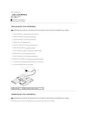
...8. Remove the display assembly (see Removing the Keyboard). 7. Remove the system board (see Removing the Optical Drive). 10. Back to Contents Page Coin-Cell Battery Dell™ Vostro™ 1510 Service Manual Removing the Coin-Cell Battery Replacing the Coin-Cell Battery Removing the Coin-Cell .... Disconnect the coin-cell battery cable connector from the system board. 1 coin-cell battery 2 coin-cell battery cable connector Replacing the Coin-Cell Battery CAUTION: Before you have completed the removal procedure Removing the Coin-Cell Battery. This procedure assumes that ...
...8. Remove the display assembly (see Removing the Keyboard). 7. Remove the system board (see Removing the Optical Drive). 10. Back to Contents Page Coin-Cell Battery Dell™ Vostro™ 1510 Service Manual Removing the Coin-Cell Battery Replacing the Coin-Cell Battery Removing the Coin-Cell .... Disconnect the coin-cell battery cable connector from the system board. 1 coin-cell battery 2 coin-cell battery cable connector Replacing the Coin-Cell Battery CAUTION: Before you have completed the removal procedure Removing the Coin-Cell Battery. This procedure assumes that ...

Service Manual
Page 9
... cover (see Replacing the System Board Assembly). 4. Replace the hard drive (see Replacing the Display Assembly). 7. Replace the display assembly (see Replacing the Hard Drive). Replace the WLAN card (see Replacing the Palm Rest). 6. 1. Replace the palm rest (see Replacing a WLAN Card). 11. Replace the keyboard (see Replacing the Fan). 10. Back to the system board. 2. Replace the fan (see Replacing the Keyboard). 8. Position the...
... cover (see Replacing the System Board Assembly). 4. Replace the hard drive (see Replacing the Display Assembly). 7. Replace the display assembly (see Replacing the Hard Drive). Replace the WLAN card (see Replacing the Palm Rest). 6. 1. Replace the palm rest (see Replacing a WLAN Card). 11. Replace the keyboard (see Replacing the Fan). 10. Back to the system board. 2. Replace the fan (see Replacing the Keyboard). 8. Position the...
Service Manual
Page 13
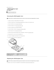
... instructions that shipped with your computer. Remove the hinge cover (see Removing the Keyboard). 6. Remove the keyboard (see Removing the Hinge Cover). 5. Back to Contents Page USB Daughter Card Dell™ Vostro™ 1510 Service Manual Removing the USB Daughter Card Replacing the USB Daughter Card Removing the USB Daughter Card CAUTION: Before you begin the...
... instructions that shipped with your computer. Remove the hinge cover (see Removing the Keyboard). 6. Remove the keyboard (see Removing the Hinge Cover). 5. Back to Contents Page USB Daughter Card Dell™ Vostro™ 1510 Service Manual Removing the USB Daughter Card Replacing the USB Daughter Card Removing the USB Daughter Card CAUTION: Before you begin the...

Service Manual
Page 14
... (see Removing the Card). 4. Connect the daughter card connector to Contents Page Replace the internal card with Bluetooth wireless technology, if installed (see Replacing the Display Assembly). 6. Replace the hinge cover (see Replacing the Keyboard). 7. Replace the keyboard (see Replacing the Hinge Cover). 8. 1. Replace the WLAN card (see Replacing the Palm Rest). 5. Back to the daughter card. 3. See Removing the...
... (see Removing the Card). 4. Connect the daughter card connector to Contents Page Replace the internal card with Bluetooth wireless technology, if installed (see Replacing the Display Assembly). 6. Replace the hinge cover (see Replacing the Keyboard). 7. Replace the keyboard (see Replacing the Hinge Cover). 8. 1. Replace the WLAN card (see Replacing the Palm Rest). 5. Back to the daughter card. 3. See Removing the...

Service Manual
Page 16
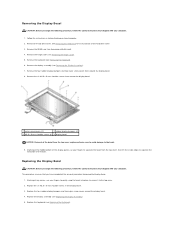
... of the computer, then lower the display into the base of the computer. 11. In sequential order, replace the four M2.5 x 5-mm screws into place. Replace the keyboard (see Replacing a WLAN Card). 12. Route the display cable and antenna cables beneath the plastic tabs on the palm ...rest. 2. Replace the WLAN card (see Replacing the Keyboard). 8. Align the display hinges with your computer. Close the display and turn the computer upside down. 10. Replace the M2.5 x 8-mm screw that the display cable and antenna cables...
... of the computer, then lower the display into the base of the computer. 11. In sequential order, replace the four M2.5 x 5-mm screws into place. Replace the keyboard (see Replacing a WLAN Card). 12. Route the display cable and antenna cables beneath the plastic tabs on the palm ...rest. 2. Replace the WLAN card (see Replacing the Keyboard). 8. Align the display hinges with your computer. Close the display and turn the computer upside down. 10. Replace the M2.5 x 8-mm screw that the display cable and antenna cables...
Service Manual
Page 17
... 2 rubber display bumpers (4) 3 M2.5 x 5-mm shoulder screws (6) 4 display bezel NOTICE: Removal of the bezel. Replace the keyboard (see Removing the Display Assembly). 7. Remove the keyboard (see Removing a WLAN Card). 4. This procedure assumes that you have completed the removal procedure Removing the Display Bezel... Starting at the middle bottom of the hard drive cover. 3. Remove the WLAN card (see Removing the Keyboard). 6. Remove the hinge cover (see Replacing the Display Assembly). 5. Starting at any corner, use your fingers to separate the bezel from the top ...
... 2 rubber display bumpers (4) 3 M2.5 x 5-mm shoulder screws (6) 4 display bezel NOTICE: Removal of the bezel. Replace the keyboard (see Removing the Display Assembly). 7. Remove the keyboard (see Removing a WLAN Card). 4. This procedure assumes that you have completed the removal procedure Removing the Display Bezel... Starting at the middle bottom of the hard drive cover. 3. Remove the WLAN card (see Removing the Keyboard). 6. Remove the hinge cover (see Replacing the Display Assembly). 5. Starting at any corner, use your fingers to separate the bezel from the top ...
Service Manual
Page 18
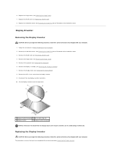
... of the hard drive cover. Remove the hinge cover (see Replacing the Hinge Cover). 7. Remove the M2 x 3-mm screw ...NOTICE: Removal of the hard drive cover. 3. Remove the hard drive cover. Replacing the Display Inverter CAUTION: Before you begin the following procedure, follow the safety..., follow the safety instructions that shipped with your computer. 1. Replace the WLAN card (see Removing a WLAN Card). 4. Display Inverter... the bezel from the display inverter. 9. Replace the hard drive cover. Remove the WLAN card (see Replacing a WLAN Card). 8. Remove the display bezel...
... of the hard drive cover. Remove the hinge cover (see Replacing the Hinge Cover). 7. Remove the M2 x 3-mm screw ...NOTICE: Removal of the hard drive cover. 3. Remove the hard drive cover. Replacing the Display Inverter CAUTION: Before you begin the following procedure, follow the safety..., follow the safety instructions that shipped with your computer. 1. Replace the WLAN card (see Removing a WLAN Card). 4. Display Inverter... the bezel from the display inverter. 9. Replace the hard drive cover. Remove the WLAN card (see Replacing a WLAN Card). 8. Remove the display bezel...
Service Manual
Page 19
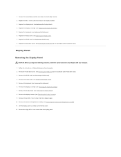
... from the display panel. Lift the display panel assembly out of the hard drive cover. 3. Replace the keyboard (see Removing the Display Assembly). 7. Remove the hard drive cover. Replace the display assembly (see Removing the Display Inverter). 9. See Removing the Hard Drive for an ... secures the display inverter. 3. Follow the instructions in Before Working on Your Computer. 2. Remove the WLAN card (see Replacing a WLAN Card). 8. Remove the keyboard (see Removing the Hinge Cover). 5. See Removing the Hard Drive for an illustration of the top cover. 12. Remove...
... from the display panel. Lift the display panel assembly out of the hard drive cover. 3. Replace the keyboard (see Removing the Display Assembly). 7. Remove the hard drive cover. Replace the display assembly (see Removing the Display Inverter). 9. See Removing the Hard Drive for an ... secures the display inverter. 3. Follow the instructions in Before Working on Your Computer. 2. Remove the WLAN card (see Replacing a WLAN Card). 8. Remove the keyboard (see Removing the Hinge Cover). 5. See Removing the Hard Drive for an illustration of the top cover. 12. Remove...

Service Manual
Page 20
... of the hard drive cover. This procedure assumes that you have completed the removal procedure Removing the Display Panel. 1. Replace the two M2 x 5-mm screws in the top cover. 3. Replace the keyboard (see Replacing the Keyboard). 10. Position the display panel assembly in the hinges. 6. See Removing the Hard Drive for an illustration of the...
... of the hard drive cover. This procedure assumes that you have completed the removal procedure Removing the Display Panel. 1. Replace the two M2 x 5-mm screws in the top cover. 3. Replace the keyboard (see Replacing the Keyboard). 10. Position the display panel assembly in the hinges. 6. See Removing the Hard Drive for an illustration of the...
Service Manual
Page 21
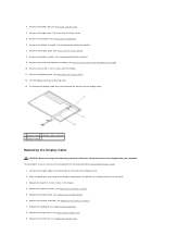
... cover. 3. Connect the display cable to the connector on the back of the display panel. 2. Replace the display assembly (see Replacing a WLAN Card). Replace the WLAN card (see Replacing the Display Assembly). 7. Replace the display bezel (see Replacing the Keyboard). 8. Replace the keyboard (see Replacing the Display Bezel). 6. Remove the display panel (see Removing the Display Inverter). 9. Remove the display...
... cover. 3. Connect the display cable to the connector on the back of the display panel. 2. Replace the display assembly (see Replacing a WLAN Card). Replace the WLAN card (see Replacing the Display Assembly). 7. Replace the display bezel (see Replacing the Keyboard). 8. Replace the keyboard (see Replacing the Display Bezel). 6. Remove the display panel (see Removing the Display Inverter). 9. Remove the display...

Service Manual
Page 22
10. See Removing the Hard Drive for an illustration of the hard drive cover. Remove the hard drive cover. Remove the keyboard (see Replacing the Display Assembly). Remove the M2 x 3-mm screw that secures the camera/microphone assembly to the connector on Your Computer. 2. ...Connect the camera/microphone cable to the top cover. 3. Replace the display assembly (see Removing the Keyboard). 6. See Removing the Hard Drive for an illustration of the hard drive cover. 3. Lift the camera/microphone out of ...
10. See Removing the Hard Drive for an illustration of the hard drive cover. Remove the hard drive cover. Remove the keyboard (see Replacing the Display Assembly). Remove the M2 x 3-mm screw that secures the camera/microphone assembly to the connector on Your Computer. 2. ...Connect the camera/microphone cable to the top cover. 3. Replace the display assembly (see Removing the Keyboard). 6. See Removing the Hard Drive for an illustration of the hard drive cover. 3. Lift the camera/microphone out of ...

Service Manual
Page 23
Replace the hard drive cover. 5. Replace the WLAN card (see Replacing the Hinge Cover). 7. Replace the hinge cover (see Replacing a WLAN Card). 8. See Removing the Hard Drive for an illustration of the hard drive cover. Replace the keyboard (see Replacing the Keyboard). 6. Back to Contents Page
Replace the hard drive cover. 5. Replace the WLAN card (see Replacing the Hinge Cover). 7. Replace the hinge cover (see Replacing a WLAN Card). 8. See Removing the Hard Drive for an illustration of the hard drive cover. Replace the keyboard (see Replacing the Keyboard). 6. Back to Contents Page
Service Manual
Page 26
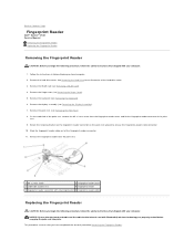
... Follow the instructions in Before Working on the palm rest upward to Contents Page Fingerprint Reader Dell™ Vostro™ 1510 Service Manual Removing the Fingerprint Reader Replacing the Fingerprint Reader Removing the Fingerprint Reader CAUTION: Before you begin the following procedure, follow the...reader cover out of palm rest 4 fingerprint reader 5 fingerprint reader connector with your computer. Remove the display assembly (see Removing the Keyboard). 6. Remove the palm rest (see Removing the Hinge Cover). 5. Remove the hinge cover (see Removing the Palm Rest). 8. ...
... Follow the instructions in Before Working on the palm rest upward to Contents Page Fingerprint Reader Dell™ Vostro™ 1510 Service Manual Removing the Fingerprint Reader Replacing the Fingerprint Reader Removing the Fingerprint Reader CAUTION: Before you begin the following procedure, follow the...reader cover out of palm rest 4 fingerprint reader 5 fingerprint reader connector with your computer. Remove the display assembly (see Removing the Keyboard). 6. Remove the palm rest (see Removing the Hinge Cover). 5. Remove the hinge cover (see Removing the Palm Rest). 8. ...
Service Manual
Page 27
.... 4. Position the fingerprint reader on the underside of the hard drive cover. Replace the palm rest (see Replacing a WLAN Card). 9. See Removing the Hard Drive for an illustration of the palm rest. 2. Replace the display assembly (see Replacing the Keyboard). 7. Replace the keyboard (see Replacing the Display Assembly). 6. Connect the fingerprint reader cable connector to the fingerprint reader...
.... 4. Position the fingerprint reader on the underside of the hard drive cover. Replace the palm rest (see Replacing a WLAN Card). 9. See Removing the Hard Drive for an illustration of the palm rest. 2. Replace the display assembly (see Replacing the Keyboard). 7. Replace the keyboard (see Replacing the Display Assembly). 6. Connect the fingerprint reader cable connector to the fingerprint reader...
Service Manual
Page 32
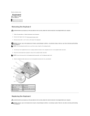
... fragile, easily dislodged, and time- NOTICE: The key caps on the keyboard are fragile, easily dislodged, and time- Exercise care when removing and handling the keyboard. consuming to replace. Back to Contents Page Keyboard Dell™ Vostro™ 1510 Service Manual Removing the Keyboard Replacing the Keyboard Removing the Keyboard CAUTION: Before you begin any of the procedures in this section...
... fragile, easily dislodged, and time- NOTICE: The key caps on the keyboard are fragile, easily dislodged, and time- Exercise care when removing and handling the keyboard. consuming to replace. Back to Contents Page Keyboard Dell™ Vostro™ 1510 Service Manual Removing the Keyboard Replacing the Keyboard Removing the Keyboard CAUTION: Before you begin any of the procedures in this section...

Service Manual
Page 33
... connector. 3. Hook the tabs along the front edge of the keyboard. 6. Replace the two M2 x 3-mm screws at the top of the keyboard beneath the front- on the upper right edge of the palm rest. 4. Replace the hinge cover (see Replacing the Hinge Cover). This procedure assumes that you have completed the removal procedure Removing...
... connector. 3. Hook the tabs along the front edge of the keyboard. 6. Replace the two M2 x 3-mm screws at the top of the keyboard beneath the front- on the upper right edge of the palm rest. 4. Replace the hinge cover (see Replacing the Hinge Cover). This procedure assumes that you have completed the removal procedure Removing...
Service Manual
Page 34
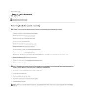
... 17. Squeeze the securing clips on Your Computer. 2. Back to Contents Page Battery Latch Assembly Dell™ Vostro™ 1510 Service Manual Removing the Battery Latch Assembly Replacing the Battery Latch Assembly Removing the Battery Latch Assembly CAUTION: Before you remove the battery release button,...shipped with Bluetooth® wireless technology to the system board (see Removing the Keyboard). 7. NOTICE: The battery-latch assembly spring is ready to ensure proper installation when the button is replaced. Remove the battery latch from the system. 16. Remove the battery lock ...
... 17. Squeeze the securing clips on Your Computer. 2. Back to Contents Page Battery Latch Assembly Dell™ Vostro™ 1510 Service Manual Removing the Battery Latch Assembly Replacing the Battery Latch Assembly Removing the Battery Latch Assembly CAUTION: Before you remove the battery release button,...shipped with Bluetooth® wireless technology to the system board (see Removing the Keyboard). 7. NOTICE: The battery-latch assembly spring is ready to ensure proper installation when the button is replaced. Remove the battery latch from the system. 16. Remove the battery lock ...


