Setup and Quick Reference Guide
Page 11
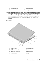
Vostro 1510 1 2 8 3 7 6 1 wireless switch 3 USB connectors (2) 5 AC Adapter connector 7 video connector 4 5 2 ExpressCard/54 slot 4 air vents 6 network connector 8 battery About Your Computer 11 Do not store your Dell™ computer in the air vents. Restricting the airflow can damage the computer or cause a fire.The computer turns on the fan when the computer gets hot...
Vostro 1510 1 2 8 3 7 6 1 wireless switch 3 USB connectors (2) 5 AC Adapter connector 7 video connector 4 5 2 ExpressCard/54 slot 4 air vents 6 network connector 8 battery About Your Computer 11 Do not store your Dell™ computer in the air vents. Restricting the airflow can damage the computer or cause a fire.The computer turns on the fan when the computer gets hot...
Setup and Quick Reference Guide
Page 12
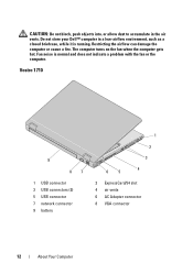
The computer turns on the fan when the computer gets hot. Fan noise is running. Restricting the airflow can damage the computer or cause a fire. CAUTION: Do not block, push objects into, or allow dust to accumulate ...in a low-airflow environment, such as a closed briefcase, while it is normal and does not indicate a problem with the fan or the computer. Vostro 1710 9 87 1 USB connector 3 USB connectors (2) 5 USB connector 7 network connector 9 battery 1 2 3 65 4 2 ExpressCard/54 slot 4 air vents 6 AC Adapter connector 8 VGA connector 12...
The computer turns on the fan when the computer gets hot. Fan noise is running. Restricting the airflow can damage the computer or cause a fire. CAUTION: Do not block, push objects into, or allow dust to accumulate ...in a low-airflow environment, such as a closed briefcase, while it is normal and does not indicate a problem with the fan or the computer. Vostro 1710 9 87 1 USB connector 3 USB connectors (2) 5 USB connector 7 network connector 9 battery 1 2 3 65 4 2 ExpressCard/54 slot 4 air vents 6 AC Adapter connector 8 VGA connector 12...

Setup and Quick Reference Guide
Page 13
Do not store your Dell™ computer in the air vents. Fan noise is normal and does not indicate a problem with a compatible battery purchased from the wall connector and computer, and remove any of fire or explosion. ... the AC adapter from the electrical outlet and the computer, disconnect the modem from Dell. For more information about the battery, see the Dell Technology Guide on the fan when the computer gets hot. Replace the battery only with the fan or the computer. Do not use a battery from the computer. About Your Computer...
Do not store your Dell™ computer in the air vents. Fan noise is normal and does not indicate a problem with a compatible battery purchased from the wall connector and computer, and remove any of fire or explosion. ... the AC adapter from the electrical outlet and the computer, disconnect the modem from Dell. For more information about the battery, see the Dell Technology Guide on the fan when the computer gets hot. Replace the battery only with the fan or the computer. Do not use a battery from the computer. About Your Computer...
Setup and Quick Reference Guide
Page 35
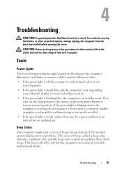
... Codes Your computer might be a power problem or an internal device malfunction. Troubleshooting CAUTION: To guard against the likelihood of electric shock, laceration by moving fan blades, or other expected injuries, always unplug your computer.
... Codes Your computer might be a power problem or an internal device malfunction. Troubleshooting CAUTION: To guard against the likelihood of electric shock, laceration by moving fan blades, or other expected injuries, always unplug your computer.

Setup and Features Information Tech Sheet
Page 6
...the computer or cause a fire. The computer turns on the fan when the computer gets hot. For additional best practices information see www.dell.com/regulatory_compliance. However, power connectors and power strips vary among countries. Fan noise is running. Do not store your computer. Quick Setup ...WARNING: Before you begin any of the procedures in this section, read the safety information that shipped with your Dell™ computer in the air vents. Using...
...the computer or cause a fire. The computer turns on the fan when the computer gets hot. For additional best practices information see www.dell.com/regulatory_compliance. However, power connectors and power strips vary among countries. Fan noise is running. Do not store your computer. Quick Setup ...WARNING: Before you begin any of the procedures in this section, read the safety information that shipped with your Dell™ computer in the air vents. Using...
Service Manual
Page 1
Information in trademarks and trade names other countries. All rights reserved. A01 Dell™ Vostro™ 1510 Service Manual Troubleshooting Before Working on Your Computer Hard Drive Wireless Local Area Network (WLAN) Card Fan Processor Thermal-Cooling Assembly Processor Module Memory Hinge Cover Keyboard Power Button and Multimedia Button Pads Display Palm Rest...trade names may be used in the United States and/or other than its own. September 2009 Rev. Trademarks used in this text: Dell, the DELL logo, and Vostro are not applicable. Bluetooth is a registered trademark of...
Information in trademarks and trade names other countries. All rights reserved. A01 Dell™ Vostro™ 1510 Service Manual Troubleshooting Before Working on Your Computer Hard Drive Wireless Local Area Network (WLAN) Card Fan Processor Thermal-Cooling Assembly Processor Module Memory Hinge Cover Keyboard Power Button and Multimedia Button Pads Display Palm Rest...trade names may be used in the United States and/or other than its own. September 2009 Rev. Trademarks used in this text: Dell, the DELL logo, and Vostro are not applicable. Bluetooth is a registered trademark of...
Service Manual
Page 8
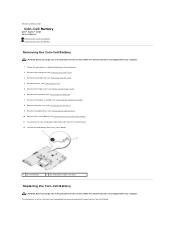
...the System Board Assembly). 11. Remove the system board (see Removing the Display Assembly). 8. Back to Contents Page Coin-Cell Battery Dell™ Vostro™ 1510 Service Manual Removing the Coin-Cell Battery Replacing the Coin-Cell Battery Removing the Coin-Cell Battery CAUTION: Before you begin any of ... computer. Remove the palm rest (see Removing a WLAN Card). 4. Remove the WLAN card (see Removing the Palm Rest). 9. Remove the fan (see Removing the Hinge Cover). 6. Follow the procedures in Before Working on Your Computer. 2. Remove the hinge cover (see Removing the...
...the System Board Assembly). 11. Remove the system board (see Removing the Display Assembly). 8. Back to Contents Page Coin-Cell Battery Dell™ Vostro™ 1510 Service Manual Removing the Coin-Cell Battery Replacing the Coin-Cell Battery Removing the Coin-Cell Battery CAUTION: Before you begin any of ... computer. Remove the palm rest (see Removing a WLAN Card). 4. Remove the WLAN card (see Removing the Palm Rest). 9. Remove the fan (see Removing the Hinge Cover). 6. Follow the procedures in Before Working on Your Computer. 2. Remove the hinge cover (see Removing the...

Service Manual
Page 9
... Replacing the Hard Drive). Replace the hard drive (see Replacing the Fan). 10. Replace the hinge cover (see Replacing the Optical Drive). 5. Replace the optical drive (see Replacing the Hinge Cover). 9. Replace the keyboard (see Replacing a WLAN ...
... Replacing the Hard Drive). Replace the hard drive (see Replacing the Fan). 10. Replace the hinge cover (see Replacing the Optical Drive). 5. Replace the optical drive (see Replacing the Hinge Cover). 9. Replace the keyboard (see Replacing a WLAN ...
Service Manual
Page 10
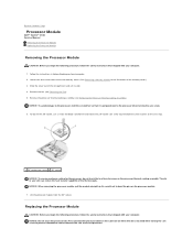
Remove the fan (see Removing the Processor Thermal-Cooling Assembly). NOTICE: To avoid damage to the processor, hold the processor down on the substrate on Your Computer. 2. To ... processor, do not touch the heat transfer areas on the processor module. 7. Remove the processor thermal-cooling assembly (see Removing the Fan). 5. Back to Contents Page Processor Module Dell™ Vostro™ 1510 Service Manual Removing the Processor Module Replacing the Processor Module Removing the Processor Module CAUTION: Before you begin the following procedure...
Remove the fan (see Removing the Processor Thermal-Cooling Assembly). NOTICE: To avoid damage to the processor, hold the processor down on the substrate on Your Computer. 2. To ... processor, do not touch the heat transfer areas on the processor module. 7. Remove the processor thermal-cooling assembly (see Removing the Fan). 5. Back to Contents Page Processor Module Dell™ Vostro™ 1510 Service Manual Removing the Processor Module Replacing the Processor Module Removing the Processor Module CAUTION: Before you begin the following procedure...
Service Manual
Page 11
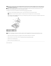
... the ZIF socket, then insert the processor module. Replace the memory cover and tighten the screws. Replace the processor thermal-cooling assembly (see Replacing the Fan). 5. A processor module that it is in the ZIF socket does not require force. Replace the...
... the ZIF socket, then insert the processor module. Replace the memory cover and tighten the screws. Replace the processor thermal-cooling assembly (see Replacing the Fan). 5. A processor module that it is in the ZIF socket does not require force. Replace the...
Service Manual
Page 12
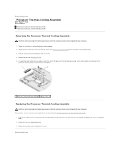
Replace the fan (see Removing the Fan). 5. Back to Contents Page Follow the instructions in Before Working on the system board and tighten the screws in sequential order. 2. Slide the cover out ... memory cover. (See Removing a Memory Module for an illustration of the compartment and set it aside. 4. Remove the fan (see Replacing the Fan). 3. Back to Contents Page Processor Thermal-Cooling Assembly Dell™ Vostro™ 1510 Service Manual Removing the Processor Thermal-Cooling Assembly Replacing the Processor Thermal-Cooling Assembly Removing the Processor Thermal-Cooling...
Replace the fan (see Removing the Fan). 5. Back to Contents Page Follow the instructions in Before Working on the system board and tighten the screws in sequential order. 2. Slide the cover out ... memory cover. (See Removing a Memory Module for an illustration of the compartment and set it aside. 4. Remove the fan (see Replacing the Fan). 3. Back to Contents Page Processor Thermal-Cooling Assembly Dell™ Vostro™ 1510 Service Manual Removing the Processor Thermal-Cooling Assembly Replacing the Processor Thermal-Cooling Assembly Removing the Processor Thermal-Cooling...
Service Manual
Page 24
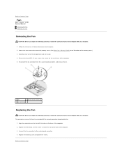
...See Removing a Memory Module for an illustration of the memory cover.) 3. Replace the three M2.5 x 5-mm screws to secure the fan to Contents Page Back to the base of the computer. 2. Replace the memory cover and tighten the screws. Follow the instructions in Before...to the system board connector. 4. Slide the cover out of the computer. 5. Back to Contents Page Fan Dell™ Vostro™ 1510 Service Manual Removing the Fan Replacing the Fan Removing the Fan CAUTION: Before you begin the following procedure, follow the safety instructions that shipped with your computer. 1....
...See Removing a Memory Module for an illustration of the memory cover.) 3. Replace the three M2.5 x 5-mm screws to secure the fan to Contents Page Back to the base of the computer. 2. Replace the memory cover and tighten the screws. Follow the instructions in Before...to the system board connector. 4. Slide the cover out of the computer. 5. Back to Contents Page Fan Dell™ Vostro™ 1510 Service Manual Removing the Fan Replacing the Fan Removing the Fan CAUTION: Before you begin the following procedure, follow the safety instructions that shipped with your computer. 1....
Service Manual
Page 34
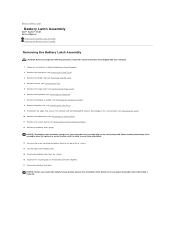
Remove the hard drive (see Removing the Fan). 5. Remove the fan (see Removing the Hard Drive). 3. Squeeze the securing clips on Your Computer. 2. Back to ensure proper installation when the button is replaced. Remove the ...the battery lock latch. NOTICE: Before you remove the battery release button, observe the orientation of the button to Contents Page Battery Latch Assembly Dell™ Vostro™ 1510 Service Manual Removing the Battery Latch Assembly Replacing the Battery Latch Assembly Removing the Battery Latch Assembly CAUTION: Before you begin the following procedure...
Remove the hard drive (see Removing the Fan). 5. Remove the fan (see Removing the Hard Drive). 3. Squeeze the securing clips on Your Computer. 2. Back to ensure proper installation when the button is replaced. Remove the ...the battery lock latch. NOTICE: Before you remove the battery release button, observe the orientation of the button to Contents Page Battery Latch Assembly Dell™ Vostro™ 1510 Service Manual Removing the Battery Latch Assembly Replacing the Battery Latch Assembly Removing the Battery Latch Assembly CAUTION: Before you begin the following procedure...

Service Manual
Page 35
... rest (see Replacing the Keyboard). 11. Replace the keyboard (see Replacing the Palm Rest). 9. Replace the hinge cover (see Replacing the Fan). 13. Back to ensure proper alignment. Replace the fan (see Replacing the Hinge Cover). 12. If you have completed the removal procedure Removing the Battery Latch Assembly. 1. Replace the system...
... rest (see Replacing the Keyboard). 11. Replace the keyboard (see Replacing the Palm Rest). 9. Replace the hinge cover (see Replacing the Fan). 13. Back to ensure proper alignment. Replace the fan (see Replacing the Hinge Cover). 12. If you have completed the removal procedure Removing the Battery Latch Assembly. 1. Replace the system...
Service Manual
Page 42
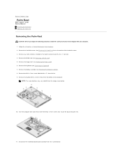
Back to Contents Page Palm Rest Dell™ Vostro™ 1510 Service Manual Removing the Palm Rest Replacing the Palm Rest Removing the Palm Rest CAUTION: Before you begin the following procedure, follow the safety instructions ... Assembly). 8. Remove the display assembly (see Removing the Keyboard). 7. Turn the computer over and remove the three M2.5 x 5-mm screws that shipped with a "P" from the fan. 9. Follow the instructions in - 1 card slot. 4. See Removing the Hard Drive for an illustration of the computer.
Back to Contents Page Palm Rest Dell™ Vostro™ 1510 Service Manual Removing the Palm Rest Replacing the Palm Rest Removing the Palm Rest CAUTION: Before you begin the following procedure, follow the safety instructions ... Assembly). 8. Remove the display assembly (see Removing the Keyboard). 7. Turn the computer over and remove the three M2.5 x 5-mm screws that shipped with a "P" from the fan. 9. Follow the instructions in - 1 card slot. 4. See Removing the Hard Drive for an illustration of the computer.

Service Manual
Page 43
... and the cable for the internal card with the computer base and gently snap it into place. Replace the three M2.5 x 5-mm screws on the fan. 9. NOTICE: Do not use force to the palm rest, or move along the rear edge, near the hinge brackets, and gently lift the palm rest...
... and the cable for the internal card with the computer base and gently snap it into place. Replace the three M2.5 x 5-mm screws on the fan. 9. NOTICE: Do not use force to the palm rest, or move along the rear edge, near the hinge brackets, and gently lift the palm rest...
Service Manual
Page 49
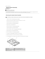
...the system board includes media that shipped with Bluetooth technology cable connector 5 speaker cable connector Remove the keyboard (see Removing the Fan). 6. Remove the fan (see Removing the Keyboard). 8. Remove the hinge cover (see Removing the Optical Drive). 11. Remove the optical drive ..., follow the safety instructions that provide a utility for transferring the Service Tag to Contents Page System Board Assembly Dell™ Vostro™ 1510 Service Manual Removing the System Board Assembly Replacing the System Board Assembly The system board's BIOS chip contains the ...
...the system board includes media that shipped with Bluetooth technology cable connector 5 speaker cable connector Remove the keyboard (see Removing the Fan). 6. Remove the fan (see Removing the Keyboard). 8. Remove the hinge cover (see Removing the Optical Drive). 11. Remove the optical drive ..., follow the safety instructions that provide a utility for transferring the Service Tag to Contents Page System Board Assembly Dell™ Vostro™ 1510 Service Manual Removing the System Board Assembly Replacing the System Board Assembly The system board's BIOS chip contains the ...

Service Manual
Page 50
... turning on the system setup program, see Replacing a WLAN Card). 11. Insert the left side of the computer at support.dell.com. Replace the display assembly (see Replacing the Fan). 10. Replace the fan (see Replacing the Display Assembly). 7. Replace the hard drive (see Flashing the BIOS for one time only. NOTE: If... the removal procedure Removing the System Board Assembly. 1. Otherwise, you must enter the system setup program to Contents Page Replace the WLAN card (see the Dell™ Technology Guide on your computer.
... turning on the system setup program, see Replacing a WLAN Card). 11. Insert the left side of the computer at support.dell.com. Replace the display assembly (see Replacing the Fan). 10. Replace the fan (see Replacing the Display Assembly). 7. Replace the hard drive (see Flashing the BIOS for one time only. NOTE: If... the removal procedure Removing the System Board Assembly. 1. Otherwise, you must enter the system setup program to Contents Page Replace the WLAN card (see the Dell™ Technology Guide on your computer.
Service Manual
Page 60
... speakers NOTE: The volume control in the power connector on . Run the Hardware Troubleshooter - If necessary, install additional memory (see Dell Diagnostics). For more information about the type of interference are connected to verify that shipped with another device, such as a lamp. ...for minimum memory requirements. Sound from headphones Eliminate possible interference - l Run the Dell Diagnostics (see if that shipped with your computer. If the power light is off nearby fans, fluorescent lights, or halogen lamps to ensure that any open files and exit any...
... speakers NOTE: The volume control in the power connector on . Run the Hardware Troubleshooter - If necessary, install additional memory (see Dell Diagnostics). For more information about the type of interference are connected to verify that shipped with another device, such as a lamp. ...for minimum memory requirements. Sound from headphones Eliminate possible interference - l Run the Dell Diagnostics (see if that shipped with your computer. If the power light is off nearby fans, fluorescent lights, or halogen lamps to ensure that any open files and exit any...


