
Setup and Quick Reference Guide
Page 37
... message appeared. C D D R I V E C O N T R O L L E R F A I L U R E - Run the hard drive tests in the proper place, and used the correct pathname. Reinstall the memory modules and, if necessary, replace them. See your Service Manual failure. Code Description (repetitive short beeps) Suggested Remedy 5 Real-time clock 1 Replace the battery (see your Service Manual at support.dell.com for more information. battery...
... message appeared. C D D R I V E C O N T R O L L E R F A I L U R E - Run the hard drive tests in the proper place, and used the correct pathname. Reinstall the memory modules and, if necessary, replace them. See your Service Manual failure. Code Description (repetitive short beeps) Suggested Remedy 5 Real-time clock 1 Replace the battery (see your Service Manual at support.dell.com for more information. battery...
Setup and Quick Reference Guide
Page 38
... a larger capacity disk. See your Service Manual at support.dell.com), and boot the computer from a CD. Reinstall the memory modules and, if necessary, replace them. D I S K D R I V E C O N F I G U R A T I Z E H A S C H A N G E D - Then, shut down the computer, reinstall the hard drive, and restart the computer. Run the Hard Disk Drive tests in filenames. The hard drive does not respond to commands from a CD. 38...
... a larger capacity disk. See your Service Manual at support.dell.com), and boot the computer from a CD. Reinstall the memory modules and, if necessary, replace them. D I S K D R I V E C O N F I G U R A T I Z E H A S C H A N G E D - Then, shut down the computer, reinstall the hard drive, and restart the computer. Run the Hard Disk Drive tests in filenames. The hard drive does not respond to commands from a CD. 38...
Setup and Quick Reference Guide
Page 40
... improperly seated. The software you want to use. 40 Troubleshooting If the hard drive is your Service Manual at support.dell.com for more information. M EMORY A L L O C A T I L A B L E - Reinstall the memory modules and, if necessary, replace them . N O B O O T D E V I C E A V A I O N E R R O R - Run the System Set tests in the Dell Diagnostics (see the software documentation. Reinstall the memory modules and, if necessary...
... improperly seated. The software you want to use. 40 Troubleshooting If the hard drive is your Service Manual at support.dell.com for more information. M EMORY A L L O C A T I L A B L E - Reinstall the memory modules and, if necessary, replace them . N O B O O T D E V I C E A V A I O N E R R O R - Run the System Set tests in the Dell Diagnostics (see the software documentation. Reinstall the memory modules and, if necessary...
Service Manual
Page 6
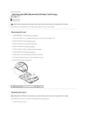
... of the hard drive cover. 3. Remove the hinge cover (see Removing the Hinge Cover). 5. This procedure assumes that connects the card to the USB board. 9. Remove the card from the card. 10. Back to Contents Page Internal Card With Bluetooth® Wireless Technology Dell™ Vostro™ 1510 Service Manual Removing the Card Replacing the Card...
... of the hard drive cover. 3. Remove the hinge cover (see Removing the Hinge Cover). 5. This procedure assumes that connects the card to the USB board. 9. Remove the card from the card. 10. Back to Contents Page Internal Card With Bluetooth® Wireless Technology Dell™ Vostro™ 1510 Service Manual Removing the Card Replacing the Card...

Service Manual
Page 7
Replace the M2 x 3-mm screw that connects the card to Contents Page See Removing the Hard Drive for an illustration of the hard drive cover. Back to the USB board. 4. Replace the hinge cover (see Replacing a WLAN Card). 9. Replace the WLAN card (see Replacing the Hinge Cover). 8. Replace the card in the card compartment. 3. Replace the display assembly (see Replacing the Keyboard). 7. Replace the hard drive cover. 2. Replace the keyboard (see Replacing the Display Assembly). 6. Replace the palm rest (see Replacing the Palm Rest). 5.
Replace the M2 x 3-mm screw that connects the card to Contents Page See Removing the Hard Drive for an illustration of the hard drive cover. Back to the USB board. 4. Replace the hinge cover (see Replacing a WLAN Card). 9. Replace the WLAN card (see Replacing the Hinge Cover). 8. Replace the card in the card compartment. 3. Replace the display assembly (see Replacing the Keyboard). 7. Replace the hard drive cover. 2. Replace the keyboard (see Replacing the Display Assembly). 6. Replace the palm rest (see Replacing the Palm Rest). 5.
Service Manual
Page 8
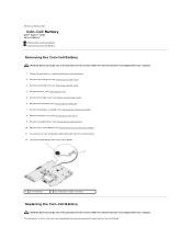
...-Cell Battery. Remove the hinge cover (see Removing the System Board Assembly). 11. Remove the hard drive (see Removing the Hard Drive). 3. Back to Contents Page Coin-Cell Battery Dell™ Vostro™ 1510 Service Manual Removing the Coin-Cell Battery Replacing the Coin-Cell Battery Removing the Coin-Cell Battery CAUTION: Before you begin any of the...
...-Cell Battery. Remove the hinge cover (see Removing the System Board Assembly). 11. Remove the hard drive (see Removing the Hard Drive). 3. Back to Contents Page Coin-Cell Battery Dell™ Vostro™ 1510 Service Manual Removing the Coin-Cell Battery Replacing the Coin-Cell Battery Removing the Coin-Cell Battery CAUTION: Before you begin any of the...

Service Manual
Page 9
... Fan). 10. Replace the fan (see Replacing a WLAN Card). 11. Replace the hard drive (see Replacing the Display Assembly). 7. Position the coin-cell battery on the system board. 3. Replace the display assembly (see Replacing the Hard Drive). Connect the coin-cell battery cable to Contents Page Replace the optical drive (see Replacing the Palm Rest). 6. Replace the palm rest (see Replacing the Optical Drive). 5. Replace the system...
... Fan). 10. Replace the fan (see Replacing a WLAN Card). 11. Replace the hard drive (see Replacing the Display Assembly). 7. Position the coin-cell battery on the system board. 3. Replace the display assembly (see Replacing the Hard Drive). Connect the coin-cell battery cable to Contents Page Replace the optical drive (see Replacing the Palm Rest). 6. Replace the palm rest (see Replacing the Optical Drive). 5. Replace the system...
Service Manual
Page 13
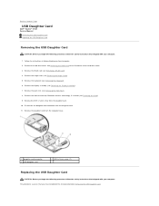
Back to Contents Page USB Daughter Card Dell™ Vostro™ 1510 Service Manual Removing the USB Daughter Card Replacing the USB Daughter Card Removing the USB Daughter Card CAUTION: Before you have completed the removal procedure Removing the USB ... See Removing the Hard Drive for an illustration of the hard drive cover. 3. Remove the internal card with your computer. Follow the instructions in Before Working on Your Computer. 2. Remove the daughter card from the computer base. 1 daughter-card connector 3 USB daughter card 2 M2.5 x 5-mm screw (1) Replacing the USB Daughter Card...
Back to Contents Page USB Daughter Card Dell™ Vostro™ 1510 Service Manual Removing the USB Daughter Card Replacing the USB Daughter Card Removing the USB Daughter Card CAUTION: Before you have completed the removal procedure Removing the USB ... See Removing the Hard Drive for an illustration of the hard drive cover. 3. Remove the internal card with your computer. Follow the instructions in Before Working on Your Computer. 2. Remove the daughter card from the computer base. 1 daughter-card connector 3 USB daughter card 2 M2.5 x 5-mm screw (1) Replacing the USB Daughter Card...

Service Manual
Page 14
... the daughter card. 3. Replace the display assembly (see Replacing the Hinge Cover). 8. Replace the hinge cover (see Replacing the Display Assembly). 6. Replace the palm rest (see Replacing a WLAN Card). 9. Replace the WLAN card (see Replacing the Palm Rest). 5. See Removing the Hard Drive for an illustration of the hard drive cover. Replace the keyboard (see Removing the Card). 4. Replace the hard drive cover. Replace the internal card...
... the daughter card. 3. Replace the display assembly (see Replacing the Hinge Cover). 8. Replace the hinge cover (see Replacing the Display Assembly). 6. Replace the palm rest (see Replacing a WLAN Card). 9. Replace the WLAN card (see Replacing the Palm Rest). 5. See Removing the Hard Drive for an illustration of the hard drive cover. Replace the keyboard (see Removing the Card). 4. Replace the hard drive cover. Replace the internal card...

Service Manual
Page 16
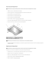
...1. Close the display and turn the computer upside down. 10. Replace the keyboard (see Replacing the Hinge Cover). 9. Replace the hard drive cover. Lift the display assembly out of the display assembly. 3. Replace the hinge cover (see Replacing the Keyboard). 8. This procedure assumes that shipped with the holes...secured beneath the plastic tabs on the palm rest. 2. 11. Display Bezel In sequential order, replace the four M2.5 x 5-mm screws in the base of the hard drive cover. NOTICE: Ensure that attaches the display assembly to the display cable connector on the palm ...
...1. Close the display and turn the computer upside down. 10. Replace the keyboard (see Replacing the Hinge Cover). 9. Replace the hard drive cover. Lift the display assembly out of the display assembly. 3. Replace the hinge cover (see Replacing the Keyboard). 8. This procedure assumes that shipped with the holes...secured beneath the plastic tabs on the palm rest. 2. 11. Display Bezel In sequential order, replace the four M2.5 x 5-mm screws in the base of the hard drive cover. NOTICE: Ensure that attaches the display assembly to the display cable connector on the palm ...
Service Manual
Page 17
... display panel, use your fingers to separate the bezel from the top cover requires extreme care to avoid damage to separate the remainder of the hard drive cover. 3. Replace the four rubber display bumpers and two mylar screw covers around the display bezel. 8. Remove the hinge cover (see Removing the Display Assembly). 7. Remove...
... display panel, use your fingers to separate the bezel from the top cover requires extreme care to avoid damage to separate the remainder of the hard drive cover. 3. Replace the four rubber display bumpers and two mylar screw covers around the display bezel. 8. Remove the hinge cover (see Removing the Display Assembly). 7. Remove...
Service Manual
Page 18
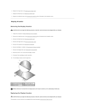
... the instructions in Before Working on Your Computer. 2. Remove the WLAN card (see Removing the Display Bezel). 8. Disconnect the two display-inverter connectors. 10. Replace the hard drive cover. Display Inverter Removing the Display Inverter CAUTION: Before you begin the following procedure, follow the safety instructions that shipped with your computer. 1. Remove the...
... the instructions in Before Working on Your Computer. 2. Remove the WLAN card (see Removing the Display Bezel). 8. Disconnect the two display-inverter connectors. 10. Replace the hard drive cover. Display Inverter Removing the Display Inverter CAUTION: Before you begin the following procedure, follow the safety instructions that shipped with your computer. 1. Remove the...
Service Manual
Page 19
... 5. Lift the display panel assembly out of the hard drive cover. See Removing the Hard Drive for an illustration of the hard drive cover. 3. Remove the hinge cover (see Removing a WLAN Card). 4. Remove the display bezel (see Replacing the Display Assembly). 5. Remove the eight M2 x... 3-mm screws from the display hinges. 10. Replace the display assembly (see Removing the Display Bezel). 8. Replace the hard drive cover. Remove the keyboard (see Removing the Camera and Microphone Assembly). 11. See Removing the Hard Drive for an illustration of the top cover. 12....
... 5. Lift the display panel assembly out of the hard drive cover. See Removing the Hard Drive for an illustration of the hard drive cover. 3. Remove the hinge cover (see Removing a WLAN Card). 4. Remove the display bezel (see Replacing the Display Assembly). 5. Remove the eight M2 x... 3-mm screws from the display hinges. 10. Replace the display assembly (see Removing the Display Bezel). 8. Replace the hard drive cover. Remove the keyboard (see Removing the Camera and Microphone Assembly). 11. See Removing the Hard Drive for an illustration of the top cover. 12....

Service Manual
Page 20
... screws in the display panel. 2. Replace the display assembly (see Replacing the Keyboard). 10. Replace the keyboard (see Replacing the Display Assembly). 9. Replace the hinge cover (see Replacing the Camera and Microphone Assembly). 4. See Removing the Hard Drive for an illustration of the hard drive cover. See Removing the Hard Drive for an illustration of the hard drive cover. Replace the eight M2 x 3-mm screws...
... screws in the display panel. 2. Replace the display assembly (see Replacing the Keyboard). 10. Replace the keyboard (see Replacing the Display Assembly). 9. Replace the hinge cover (see Replacing the Camera and Microphone Assembly). 4. See Removing the Hard Drive for an illustration of the hard drive cover. See Removing the Hard Drive for an illustration of the hard drive cover. Replace the eight M2 x 3-mm screws...

Service Manual
Page 22
... Camera and Microphone Assembly. 1. See Removing the Hard Drive for an illustration of the hard drive cover. Remove the WLAN card (see Replacing the Display Bezel). 4. Remove the display bezel (see Removing the Display Assembly). 7. Replace the hard drive cover. Remove the display assembly (see Removing the... the safety instructions that secures the camera/microphone assembly. 9. Lift the camera/microphone out of the hard drive cover. 3. Follow the instructions in the top cover and replace the M2 x 3- Remove the M2 x 3-mm screw that shipped with your computer. mm screw...
... Camera and Microphone Assembly. 1. See Removing the Hard Drive for an illustration of the hard drive cover. Remove the WLAN card (see Replacing the Display Bezel). 4. Remove the display bezel (see Removing the Display Assembly). 7. Replace the hard drive cover. Remove the display assembly (see Removing the... the safety instructions that secures the camera/microphone assembly. 9. Lift the camera/microphone out of the hard drive cover. 3. Follow the instructions in the top cover and replace the M2 x 3- Remove the M2 x 3-mm screw that shipped with your computer. mm screw...

Service Manual
Page 23
Replace the keyboard (see Replacing the Hinge Cover). 7. See Removing the Hard Drive for an illustration of the hard drive cover. Replace the hinge cover (see Replacing the Keyboard). 6. Replace the hard drive cover. Back to Contents Page Replace the WLAN card (see Replacing a WLAN Card). 8. 5.
Replace the keyboard (see Replacing the Hinge Cover). 7. See Removing the Hard Drive for an illustration of the hard drive cover. Replace the hinge cover (see Replacing the Keyboard). 6. Replace the hard drive cover. Back to Contents Page Replace the WLAN card (see Replacing a WLAN Card). 8. 5.
Service Manual
Page 26
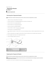
... of palm rest 4 fingerprint reader 5 fingerprint reader connector with retaining bracket 6 fingerprint reader cable Replacing the Fingerprint Reader CAUTION: Before you begin the following procedure, follow the safety instructions that shipped ...hard drive cover. Remove the hinge cover (see Removing the Display Assembly). 7. Remove the display assembly (see Removing the Hinge Cover). 5. Remove the palm rest (see Removing the Palm Rest). 8. Follow the instructions in Before Working on the palm rest upward to Contents Page Fingerprint Reader Dell™ Vostro™ 1510...
... of palm rest 4 fingerprint reader 5 fingerprint reader connector with retaining bracket 6 fingerprint reader cable Replacing the Fingerprint Reader CAUTION: Before you begin the following procedure, follow the safety instructions that shipped ...hard drive cover. Remove the hinge cover (see Removing the Display Assembly). 7. Remove the display assembly (see Removing the Hinge Cover). 5. Remove the palm rest (see Removing the Palm Rest). 8. Follow the instructions in Before Working on the palm rest upward to Contents Page Fingerprint Reader Dell™ Vostro™ 1510...
Service Manual
Page 27
... downward to Contents Page Replace the fingerprint reader cover and replace the M2 x 3-mm screw that secures the cover to the palm rest. 4. Position the fingerprint reader on the underside of the hard drive cover. Replace the hinge cover (see Replacing the Hinge Cover). 8. See Removing the Hard Drive for an illustration of the palm rest. 2. Replace the hard drive cover.
... downward to Contents Page Replace the fingerprint reader cover and replace the M2 x 3-mm screw that secures the cover to the palm rest. 4. Position the fingerprint reader on the underside of the hard drive cover. Replace the hinge cover (see Replacing the Hinge Cover). 8. See Removing the Hard Drive for an illustration of the palm rest. 2. Replace the hard drive cover.
Service Manual
Page 28
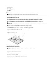
... tab to the hard drive bracket. 9. Remove the two screws securing the hard drive to release the hard drive. 7. CAUTION: Do not touch the metal housing of the procedures in protective antistatic packaging. 5. Back to Contents Page Hard Drive Dell™ Vostro™ 1510 Service Manual Removing the Hard Drive Replacing the Hard Drive NOTE: Dell does not guarantee compatibility or provide support for hard drives obtained from the...
... tab to the hard drive bracket. 9. Remove the two screws securing the hard drive to release the hard drive. 7. CAUTION: Do not touch the metal housing of the procedures in protective antistatic packaging. 5. Back to Contents Page Hard Drive Dell™ Vostro™ 1510 Service Manual Removing the Hard Drive Replacing the Hard Drive NOTE: Dell does not guarantee compatibility or provide support for hard drives obtained from the...

Service Manual
Page 29
... to the connector. For information on reinstalling drivers and utilities, see the Setup and Quick Reference Guide for your computer on support.dell.com. NOTICE: Hard drives are extremely fragile. 1 hard drive Replacing the Hard Drive CAUTION: Before you have completed the removal procedure Removing the Hard Drive. 1. Excessive force may result in the bracket. 2. Replace the hard drive cover aligning the notches. 5.
... to the connector. For information on reinstalling drivers and utilities, see the Setup and Quick Reference Guide for your computer on support.dell.com. NOTICE: Hard drives are extremely fragile. 1 hard drive Replacing the Hard Drive CAUTION: Before you have completed the removal procedure Removing the Hard Drive. 1. Excessive force may result in the bracket. 2. Replace the hard drive cover aligning the notches. 5.


