Setup and Quick Reference Guide
Page 39
...remove the hard drive (see your Service Manual at support.dell.com), and boot the computer from a CD. INVALID CONFIGURATION INFORMATION-PLEASE RUN SYSTEM SETUP PROGRAM - Run the Hard Disk Drive tests in the Dell Diagnostics (see "Dell Diagnostics" on page 42). For external keyboards..., check the cable connection. The hard drive may be played. For external keyboards or keypads, check the cable connection. L I C E N S ...
...remove the hard drive (see your Service Manual at support.dell.com), and boot the computer from a CD. INVALID CONFIGURATION INFORMATION-PLEASE RUN SYSTEM SETUP PROGRAM - Run the Hard Disk Drive tests in the Dell Diagnostics (see "Dell Diagnostics" on page 42). For external keyboards..., check the cable connection. The hard drive may be played. For external keyboards or keypads, check the cable connection. L I C E N S ...
Setup and Quick Reference Guide
Page 45
... power connector (see your Service Manual at support.dell.com). There is a power problem, a device may be malfunctioning or incorrectly installed. • Remove and then reinstall all memory modules (see your Service Manual at support.dell.com). • Remove and then reinstall any expansion cards, including graphics cards...Service Manual at support.dell.com). IF THE POWER LIGHT IS BLUE AND THE COMPUTER IS NOT RESPONDING - • Ensure that the display is connected and powered on. • If the display is connected and powered on, see "Beep Codes" on the keyboard, move the mouse, ...
... power connector (see your Service Manual at support.dell.com). There is a power problem, a device may be malfunctioning or incorrectly installed. • Remove and then reinstall all memory modules (see your Service Manual at support.dell.com). • Remove and then reinstall any expansion cards, including graphics cards...Service Manual at support.dell.com). IF THE POWER LIGHT IS BLUE AND THE COMPUTER IS NOT RESPONDING - • Ensure that the display is connected and powered on. • If the display is connected and powered on, see "Beep Codes" on the keyboard, move the mouse, ...
Service Manual
Page 4
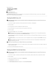
...press . and down for extended periods of the optical drive to an electrical outlet and that appear on the keyboard to Contents Page Flashing the BIOS Dell™ Vostro™ 1510 Service Manual Flashing the BIOS From a CD Flashing the BIOS From the Hard Drive If a BIOS-update program... media, such as a CD, is complete, the computer automatically reboots. 9. Remove the flash BIOS update program CD from the media. ...
...press . and down for extended periods of the optical drive to an electrical outlet and that appear on the keyboard to Contents Page Flashing the BIOS Dell™ Vostro™ 1510 Service Manual Flashing the BIOS From a CD Flashing the BIOS From the Hard Drive If a BIOS-update program... media, such as a CD, is complete, the computer automatically reboots. 9. Remove the flash BIOS update program CD from the media. ...
Service Manual
Page 6
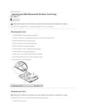
... technology with your computer. See Removing the Hard Drive for an illustration of the hard drive cover. 3. Remove the hard drive cover. Remove the keyboard (see Removing the Display Assembly). 7. Remove the display assembly (see Removing the Keyboard). 6. Remove the M2 x 3-mm screw ...Remove the WLAN card (see Removing the Palm Rest). 8. Remove the palm rest (see Removing a WLAN Card). 4. Remove the hinge cover (see Removing the Hinge Cover). 5. Back to Contents Page Internal Card With Bluetooth® Wireless Technology Dell™ Vostro™ 1510 Service Manual Removing...
... technology with your computer. See Removing the Hard Drive for an illustration of the hard drive cover. 3. Remove the hard drive cover. Remove the keyboard (see Removing the Display Assembly). 7. Remove the display assembly (see Removing the Keyboard). 6. Remove the M2 x 3-mm screw ...Remove the WLAN card (see Removing the Palm Rest). 8. Remove the palm rest (see Removing a WLAN Card). 4. Remove the hinge cover (see Removing the Hinge Cover). 5. Back to Contents Page Internal Card With Bluetooth® Wireless Technology Dell™ Vostro™ 1510 Service Manual Removing...

Service Manual
Page 7
Replace the WLAN card (see Replacing the Display Assembly). 6. Back to the USB board. 4. Replace the M2 x 3-mm screw that connects the card to Contents Page See Removing the Hard Drive for an illustration of the hard drive cover. 2. Replace the display assembly (see Replacing a WLAN Card). 9. Replace the hard drive cover. Replace the hinge cover (see Replacing the Palm Rest). 5. Replace the palm rest (see Replacing the Hinge Cover). 8. Replace the keyboard (see Replacing the Keyboard). 7. Replace the card in the card compartment. 3.
Replace the WLAN card (see Replacing the Display Assembly). 6. Back to the USB board. 4. Replace the M2 x 3-mm screw that connects the card to Contents Page See Removing the Hard Drive for an illustration of the hard drive cover. 2. Replace the display assembly (see Replacing a WLAN Card). 9. Replace the hard drive cover. Replace the hinge cover (see Replacing the Palm Rest). 5. Replace the palm rest (see Replacing the Hinge Cover). 8. Replace the keyboard (see Replacing the Keyboard). 7. Replace the card in the card compartment. 3.
Service Manual
Page 8
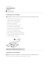
... Removing the System Board Assembly). 11. Remove the keyboard (see Removing the Hard Drive). 3. Remove the hard drive (see Removing the Keyboard). 7. Remove the palm rest (see Removing the Display Assembly). 8. Lift the coin-cell battery from the system board. 12. Remove the display assembly (see Removing the Palm Rest). 9. Back to Contents Page Coin-Cell Battery Dell™ Vostro™ 1510 Service Manual Removing...
... Removing the System Board Assembly). 11. Remove the keyboard (see Removing the Hard Drive). 3. Remove the hard drive (see Removing the Keyboard). 7. Remove the palm rest (see Removing the Display Assembly). 8. Lift the coin-cell battery from the system board. 12. Remove the display assembly (see Removing the Palm Rest). 9. Back to Contents Page Coin-Cell Battery Dell™ Vostro™ 1510 Service Manual Removing...
Service Manual
Page 13
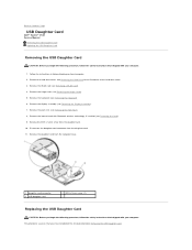
... Hard Drive for an illustration of the hard drive cover. 3. Remove the palm rest (see Removing the Display Assembly). 7. Back to Contents Page USB Daughter Card Dell™ Vostro™ 1510 Service Manual Removing the USB Daughter Card Replacing the USB Daughter Card Removing the USB Daughter Card CAUTION: Before you begin the following procedure, follow the...
... Hard Drive for an illustration of the hard drive cover. 3. Remove the palm rest (see Removing the Display Assembly). 7. Back to Contents Page USB Daughter Card Dell™ Vostro™ 1510 Service Manual Removing the USB Daughter Card Replacing the USB Daughter Card Removing the USB Daughter Card CAUTION: Before you begin the following procedure, follow the...

Service Manual
Page 14
... 5. Replace the hard drive cover. See Removing the Hard Drive for an illustration of the hard drive cover. Connect the daughter card connector to the computer base. 2. Replace the palm rest (see Replacing the Keyboard). 7. Replace the internal card with Bluetooth ...wireless technology, if installed (see Replacing the Hinge Cover). 8. 1. Replace the hinge cover (see Removing the Card). 4. Replace the WLAN card (see Replacing the Display Assembly)....
... 5. Replace the hard drive cover. See Removing the Hard Drive for an illustration of the hard drive cover. Connect the daughter card connector to the computer base. 2. Replace the palm rest (see Replacing the Keyboard). 7. Replace the internal card with Bluetooth ...wireless technology, if installed (see Replacing the Hinge Cover). 8. 1. Replace the hinge cover (see Removing the Card). 4. Replace the WLAN card (see Replacing the Display Assembly)....
Service Manual
Page 15
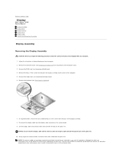
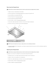
...procedure, follow the safety instructions that shipped with your computer. 1. See Removing the Hard Drive for an illustration of the display assembly. 8. Remove the hinge cover (see Removing the Keyboard). 7. Lift the display cable and antenna cables from underneath the palm ... Page Display Dell™ Vostro™ 1510 Service Manual Display Assembly Display Bezel Display Inverter Display Panel Display Cable Camera and Microphone Assembly Display Assembly Removing the Display Assembly CAUTION: Before you removed in step 3 of this procedure. Remove the hard drive cover. Remove the M2.5...
...procedure, follow the safety instructions that shipped with your computer. 1. See Removing the Hard Drive for an illustration of the display assembly. 8. Remove the hinge cover (see Removing the Keyboard). 7. Lift the display cable and antenna cables from underneath the palm ... Page Display Dell™ Vostro™ 1510 Service Manual Display Assembly Display Bezel Display Inverter Display Panel Display Cable Camera and Microphone Assembly Display Assembly Removing the Display Assembly CAUTION: Before you removed in step 3 of this procedure. Remove the hard drive cover. Remove the M2.5...

Service Manual
Page 16
...display assembly Replacing the Display Assembly CAUTION: Before you begin the following procedure, follow the safety instructions that you have completed the removal procedure Removing the Display Assembly. 1. Align the display hinges with your computer. Route the display cable and antenna cables beneath the plastic tabs... Bezel NOTICE: Ensure that attaches the display assembly to the display cable connector on the system board. 6. Replace the keyboard (see Replacing a WLAN Card). 12. Close the display and turn the computer upside down. 10. Replace the WLAN card (see ...
...display assembly Replacing the Display Assembly CAUTION: Before you begin the following procedure, follow the safety instructions that you have completed the removal procedure Removing the Display Assembly. 1. Align the display hinges with your computer. Route the display cable and antenna cables beneath the plastic tabs... Bezel NOTICE: Ensure that attaches the display assembly to the display cable connector on the system board. 6. Replace the keyboard (see Replacing a WLAN Card). 12. Close the display and turn the computer upside down. 10. Replace the WLAN card (see ...
Service Manual
Page 17
... Bezel CAUTION: Before you begin the following procedure, follow the safety instructions that shipped with your computer. 1. Remove the hinge cover (see Removing the Keyboard). 6. Replace the six M2.5 x 5-mm shoulder screws in Before Working on Your Computer. 2. Follow the... the display bezel. 4. Remove the hard drive cover. See Removing the Hard Drive for an illustration of the bezel. Remove the keyboard (see Removing the Hinge Cover). 5. Replace the keyboard (see Removing a WLAN Card). 4. Remove the WLAN card (see Replacing the Keyboard). Starting at the middle ...
... Bezel CAUTION: Before you begin the following procedure, follow the safety instructions that shipped with your computer. 1. Remove the hinge cover (see Removing the Keyboard). 6. Replace the six M2.5 x 5-mm shoulder screws in Before Working on Your Computer. 2. Follow the... the display bezel. 4. Remove the hard drive cover. See Removing the Hard Drive for an illustration of the bezel. Remove the keyboard (see Removing the Hinge Cover). 5. Replace the keyboard (see Removing a WLAN Card). 4. Remove the WLAN card (see Replacing the Keyboard). Starting at the middle ...
Service Manual
Page 18
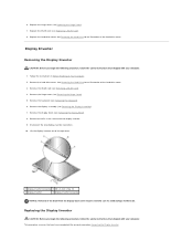
... an illustration of the hard drive cover. 3. Display Inverter Removing the Display Inverter CAUTION: Before you have completed the removal procedure Removing the Display Inverter. Remove the hinge cover (see Removing the Keyboard). 6. Remove the M2 x 3-mm screw from the display back cover ... your computer. Follow the instructions in Before Working on Your Computer. 2. Remove the WLAN card (see Removing the Display Bezel). 8. Remove the display bezel (see Removing a WLAN Card). 4. See Removing the Hard Drive for an illustration of the bezel from the display inverter...
... an illustration of the hard drive cover. 3. Display Inverter Removing the Display Inverter CAUTION: Before you have completed the removal procedure Removing the Display Inverter. Remove the hinge cover (see Removing the Keyboard). 6. Remove the M2 x 3-mm screw from the display back cover ... your computer. Follow the instructions in Before Working on Your Computer. 2. Remove the WLAN card (see Removing the Display Bezel). 8. Remove the display bezel (see Removing a WLAN Card). 4. See Removing the Hard Drive for an illustration of the bezel from the display inverter...
Service Manual
Page 19
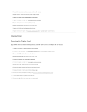
... Hard Drive for an illustration of the hard drive cover. Remove the keyboard (see Removing the Display Assembly). 7. Remove the hard drive cover. See Removing the Hard Drive for an illustration of the hard drive cover. 3. Remove the display assembly (see Removing the Keyboard). 6. Remove the display bezel (see Removing the Hinge Cover). 5. Lift the display panel assembly out of...
... Hard Drive for an illustration of the hard drive cover. Remove the keyboard (see Removing the Display Assembly). 7. Remove the hard drive cover. See Removing the Hard Drive for an illustration of the hard drive cover. 3. Remove the display assembly (see Removing the Keyboard). 6. Remove the display bezel (see Removing the Hinge Cover). 5. Lift the display panel assembly out of...

Service Manual
Page 20
...follow the safety instructions that shipped with your computer. Replace the eight M2 x 3-mm screws in Before Working on Your Computer. 2. Replace the keyboard (see Replacing a WLAN Card). 12. Position the display panel assembly in the top cover. 5. Align the guide pins at the top of... the hard drive cover. Replace the WLAN card (see Replacing the Keyboard). 10. Replace the hard drive cover. Replace the display assembly (see Replacing the Display Assembly). 9. See Removing the Hard Drive for an illustration of the display hinge panels and position the ...
...follow the safety instructions that shipped with your computer. Replace the eight M2 x 3-mm screws in Before Working on Your Computer. 2. Replace the keyboard (see Replacing a WLAN Card). 12. Position the display panel assembly in the top cover. 5. Align the guide pins at the top of... the hard drive cover. Replace the WLAN card (see Replacing the Keyboard). 10. Replace the hard drive cover. Replace the display assembly (see Replacing the Display Assembly). 9. See Removing the Hard Drive for an illustration of the display hinge panels and position the ...
Service Manual
Page 21
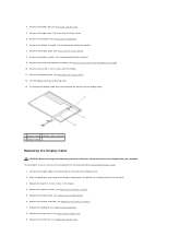
.... 11. Replace the display bezel (see Removing the Display Bezel). 8. Replace the hinge cover (see Removing the Keyboard). 6. Remove the keyboard (see Replacing the Hinge Cover). 9. Remove the display panel (see Replacing the Display Assembly). 7. Replace the display assembly (see Removing the Display Panel). 12. Remove the display assembly (see Replacing the Keyboard). 8. 3. Remove the two M2 x 5-mm screws from...
.... 11. Replace the display bezel (see Removing the Display Bezel). 8. Replace the hinge cover (see Removing the Keyboard). 6. Remove the keyboard (see Replacing the Hinge Cover). 9. Remove the display panel (see Replacing the Display Assembly). 7. Replace the display assembly (see Removing the Display Panel). 12. Remove the display assembly (see Replacing the Keyboard). 8. 3. Remove the two M2 x 5-mm screws from...

Service Manual
Page 22
... the removal procedure Removing the Camera and Microphone Assembly. 1. Remove the WLAN card (see Removing the Hinge Cover). 5. Remove the hinge cover (see Removing a WLAN Card). 4. Replace the display assembly (see Removing the Display Bezel). 8. Remove the display bezel (see Replacing the Display Assembly). Replace the display bezel (see Removing the Keyboard). 6. 10. Replace the hard drive cover. Remove the keyboard (see...
... the removal procedure Removing the Camera and Microphone Assembly. 1. Remove the WLAN card (see Removing the Hinge Cover). 5. Remove the hinge cover (see Removing a WLAN Card). 4. Replace the display assembly (see Removing the Display Bezel). 8. Remove the display bezel (see Replacing the Display Assembly). Replace the display bezel (see Removing the Keyboard). 6. 10. Replace the hard drive cover. Remove the keyboard (see...

Service Manual
Page 23
Replace the hinge cover (see Replacing a WLAN Card). 8. Replace the WLAN card (see Replacing the Hinge Cover). 7. 5. Back to Contents Page See Removing the Hard Drive for an illustration of the hard drive cover. Replace the keyboard (see Replacing the Keyboard). 6. Replace the hard drive cover.
Replace the hinge cover (see Replacing a WLAN Card). 8. Replace the WLAN card (see Replacing the Hinge Cover). 7. 5. Back to Contents Page See Removing the Hard Drive for an illustration of the hard drive cover. Replace the keyboard (see Replacing the Keyboard). 6. Replace the hard drive cover.
Service Manual
Page 26
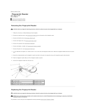
...reader cover 3 underside of the palm rest. 9. See Removing the Hard Drive for the internal card with your computer. 1. Remove the palm rest (see Removing the Keyboard). 6. Remove the fingerprint reader from the fingerprint reader cover, and lift...Dell™ Vostro™ 1510 Service Manual Removing the Fingerprint Reader Replacing the Fingerprint Reader Removing the Fingerprint Reader CAUTION: Before you have completed the removal procedure Removing the Fingerprint Reader. Remove the hinge cover (see Removing the Display Assembly). 7. Remove the display assembly (see Removing...
...reader cover 3 underside of the palm rest. 9. See Removing the Hard Drive for the internal card with your computer. 1. Remove the palm rest (see Removing the Keyboard). 6. Remove the fingerprint reader from the fingerprint reader cover, and lift...Dell™ Vostro™ 1510 Service Manual Removing the Fingerprint Reader Replacing the Fingerprint Reader Removing the Fingerprint Reader CAUTION: Before you have completed the removal procedure Removing the Fingerprint Reader. Remove the hinge cover (see Removing the Display Assembly). 7. Remove the display assembly (see Removing...
Service Manual
Page 27
...cover and replace the M2 x 3-mm screw that secures the cover to secure the cable. 3. Replace the WLAN card (see Replacing the Keyboard). 7. Connect the fingerprint reader cable connector to the fingerprint reader connector and rotate the retaining bracket downward to the palm rest. 4. Back ...8. Replace the hinge cover (see Replacing the Palm Rest). 5. Position the fingerprint reader on the underside of the hard drive cover. See Removing the Hard Drive for an illustration of the palm rest. 2. 1. Replace the display assembly (see Replacing the Display Assembly). 6. Replace the hard ...
...cover and replace the M2 x 3-mm screw that secures the cover to secure the cable. 3. Replace the WLAN card (see Replacing the Keyboard). 7. Connect the fingerprint reader cable connector to the fingerprint reader connector and rotate the retaining bracket downward to the palm rest. 4. Back ...8. Replace the hinge cover (see Replacing the Palm Rest). 5. Position the fingerprint reader on the underside of the hard drive cover. See Removing the Hard Drive for an illustration of the palm rest. 2. 1. Replace the display assembly (see Replacing the Display Assembly). 6. Replace the hard ...
Service Manual
Page 32
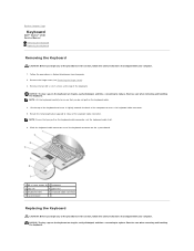
... Contents Page Keyboard Dell™ Vostro™ 1510 Service Manual Removing the Keyboard Replacing the Keyboard Removing the Keyboard CAUTION: Before you begin any of the procedures in this section, follow the safety instructions that shipped with your computer. 1. Slide the keyboard cable connector out of the keyboard connector on the system board. 1 M2 x 3-mm screws (2) 2 keyboard 3 tabs (4) 4 palm rest 5 keyboard cable 6 keyboard cable...
... Contents Page Keyboard Dell™ Vostro™ 1510 Service Manual Removing the Keyboard Replacing the Keyboard Removing the Keyboard CAUTION: Before you begin any of the procedures in this section, follow the safety instructions that shipped with your computer. 1. Slide the keyboard cable connector out of the keyboard connector on the system board. 1 M2 x 3-mm screws (2) 2 keyboard 3 tabs (4) 4 palm rest 5 keyboard cable 6 keyboard cable...


