Service Manual
Page 4
...23 Mirror Motor Test 3-23 Sensor Monitor Test 3-24 Cooling Fan / Fuser Control Test 3-25 Erase Lamp Test 3-26 Reset Test Mode 3-26 Engine Firmware 3-26 Printer Operation 3-27 Electrophotographic Process 3-27 Paper Feeding, Transferring and Fusing 3-27... Paper Path/Sensor Locations 3-28 Cable Locations 3-29 Repair Information 4-1 Handling ESD-Sensitive Parts 4-1 Adjustment Procedures 4-2 Printhead Assembly 4-2 Paper Alignment 4-3 Removal Procedures...
...23 Mirror Motor Test 3-23 Sensor Monitor Test 3-24 Cooling Fan / Fuser Control Test 3-25 Erase Lamp Test 3-26 Reset Test Mode 3-26 Engine Firmware 3-26 Printer Operation 3-27 Electrophotographic Process 3-27 Paper Feeding, Transferring and Fusing 3-27... Paper Path/Sensor Locations 3-28 Cable Locations 3-29 Repair Information 4-1 Handling ESD-Sensitive Parts 4-1 Adjustment Procedures 4-2 Printhead Assembly 4-2 Paper Alignment 4-3 Removal Procedures...
Service Manual
Page 5
... Option Tray Board 5-12 Parts Catalog 6-1 Assembly 1: Covers 6-2 Assembly 2: Frame 6-6 Assembly 3: Printhead 6-8 Assembly 4: Paper Feed - Multipurpose Unit 6-10 Assembly 5: Paper Feed - Output 6-14 Assembly 7: Main Drive 6-16 Assembly 8: Developer Drive 6-18 Assembly 9: Fuser 6-20 Assembly 10: Transfer 6-24 Assembly 11: Charging 6-26 Assembly 12: Electronics 6-28 Assembly 13: 250-Sheet Tray 6-34 Assembly 14: 500-Sheet Tray 6-36 Assembly 15: Options 6-40 Index I-1 v Alignment 6-12...
... Option Tray Board 5-12 Parts Catalog 6-1 Assembly 1: Covers 6-2 Assembly 2: Frame 6-6 Assembly 3: Printhead 6-8 Assembly 4: Paper Feed - Multipurpose Unit 6-10 Assembly 5: Paper Feed - Output 6-14 Assembly 7: Main Drive 6-16 Assembly 8: Developer Drive 6-18 Assembly 9: Fuser 6-20 Assembly 10: Transfer 6-24 Assembly 11: Charging 6-26 Assembly 12: Electronics 6-28 Assembly 13: 250-Sheet Tray 6-34 Assembly 14: 500-Sheet Tray 6-36 Assembly 15: Options 6-40 Index I-1 v Alignment 6-12...
Service Manual
Page 40
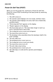
..."Ready" appears on . 9. The main drive motor turns on the display. 6. The cooling fan turns on the display. 5. The exit rollers turn the printer On, it performs a Power-On Self Test. The main drive motor turns off . 16. The operator panel displays one row of diamonds, and then clears...Self Test" appears on and runs slowly. 13. The printhead mirror motor turns off . 14. The LED comes on . The fuser lamp turns on . 2. The developer drive assembly drives the developer shaft in the toner cartridge. 10. The printhead mirror motor turns on. 12. Check for correct POST functioning ...
..."Ready" appears on . 9. The main drive motor turns on the display. 6. The cooling fan turns on the display. 5. The exit rollers turn the printer On, it performs a Power-On Self Test. The main drive motor turns off . 16. The operator panel displays one row of diamonds, and then clears...Self Test" appears on and runs slowly. 13. The printhead mirror motor turns off . 14. The LED comes on . The fuser lamp turns on . 2. The developer drive assembly drives the developer shaft in the toner cartridge. 10. The printhead mirror motor turns on. 12. Check for correct POST functioning ...

Service Manual
Page 49
...codes 920, 921, and 922 may display for correct installation. Check the cable connection to the engine board, J13 for a cold fuser failure. Service Tip: Set the Fuser Temperature to slow or fast. Diagnostic Information 2-23 Turn the cooling fan on again. If correct, replace the fan. A 920 ...incorrect, replace the engine board. The main fan runs continuously when the printer is powered on the engine board and at the main fan assembly. 4045-XXX Fan Service Check Check the cable connections at J13 on unless the printer is in the Hardware Test Mode. The voltage measures +24 V ...
...codes 920, 921, and 922 may display for correct installation. Check the cable connection to the engine board, J13 for a cold fuser failure. Service Tip: Set the Fuser Temperature to slow or fast. Diagnostic Information 2-23 Turn the cooling fan on again. If correct, replace the fan. A 920 ...incorrect, replace the engine board. The main fan runs continuously when the printer is powered on the engine board and at the main fan assembly. 4045-XXX Fan Service Check Check the cable connections at J13 on unless the printer is in the Hardware Test Mode. The voltage measures +24 V ...
Service Manual
Page 50
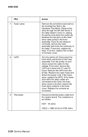
... the cable for line voltage. If the fuses open after the lamp cables are connected to the fuser, the fuser lamp circuit is as necessary. Disconnect the thermistor cable from the printer. Disconnect the fuser lamp connectors at the fuser assembly. Remove the LVPS from the engine board. Replace any open , replace the LVPS. Inspect the...
... the cable for line voltage. If the fuses open after the lamp cables are connected to the fuser, the fuser lamp circuit is as necessary. Disconnect the thermistor cable from the printer. Disconnect the fuser lamp connectors at the fuser assembly. Remove the LVPS from the engine board. Replace any open , replace the LVPS. Inspect the...
Service Manual
Page 51
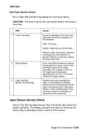
... thermistor circuit for signs of the sensor. Examine the fuser assembly for the fuser assembly. Error code 924 indicates the engine board detects an open to closed as necessary or replace the fuser assembly. The display changes from J8-6 and J8-7 to the thermistor assembly. 4045-XXX Hot Fuser Service Check Error codes 923 and 924 may be...
... thermistor circuit for signs of the sensor. Examine the fuser assembly for the fuser assembly. Error code 924 indicates the engine board detects an open to closed as necessary or replace the fuser assembly. The display changes from J8-6 and J8-7 to the thermistor assembly. 4045-XXX Hot Fuser Service Check Error codes 923 and 924 may be...
Service Manual
Page 55
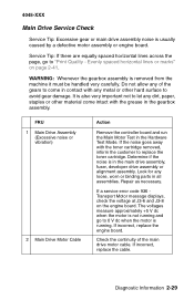
WARNING: Whenever the gearbox assembly is in the main drive assembly, fuser, developer drive assembly or alignment assembly. FRU 1 Main Drive Assembly (Excessive noise or vibration) 2 Main Drive Motor Cable Action Remove the controller board and run the Main Motor Test in all assemblies. If incorrect, replace the engine ...the motor is running and go to "Print Quality - 4045-XXX Main Drive Service Check Service Tip: Excessive gear or main drive assembly noise is also very important not to let any dirt, paper, staples or other hard surface to avoid gear damage. Service Tip...
WARNING: Whenever the gearbox assembly is in the main drive assembly, fuser, developer drive assembly or alignment assembly. FRU 1 Main Drive Assembly (Excessive noise or vibration) 2 Main Drive Motor Cable Action Remove the controller board and run the Main Motor Test in all assemblies. If incorrect, replace the engine ...the motor is running and go to "Print Quality - 4045-XXX Main Drive Service Check Service Tip: Excessive gear or main drive assembly noise is also very important not to let any dirt, paper, staples or other hard surface to avoid gear damage. Service Tip...
Service Manual
Page 72
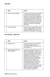
... as necessary. Clean with the wire. Check the continuity of wear or contamination. 4045-XXX FRU 1 Erase Lamp Assembly 2 Fuser Assembly Print Quality - FRU 1 Transfer Roll 2 Right Side Transfer Roll Arm Assembly Action Check the right end of the transfer roll shaft for signs of the transfer roll... assembly cable to be retained and deposited on the cable. Check the fuser assembly for signs of the cable from the bearing to make ...
... as necessary. Clean with the wire. Check the continuity of wear or contamination. 4045-XXX FRU 1 Erase Lamp Assembly 2 Fuser Assembly Print Quality - FRU 1 Transfer Roll 2 Right Side Transfer Roll Arm Assembly Action Check the right end of the transfer roll shaft for signs of the transfer roll... assembly cable to be retained and deposited on the cable. Check the fuser assembly for signs of the cable from the bearing to make ...
Service Manual
Page 73
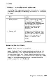
4045-XXX Print Quality - FRU 1 Fuser Assembly 2 Transfer Roll Action Toner is generally caused by a toner buildup on page 3-11... toner. The test provides failure information on the backside of toner. This problem is being carried through the printer on the display for any signs of the media. Clean the area and run another copy. Diagnostic Information ...buildup of the paper. If the test indicates a problem, replace the controller board. The test helps isolate the printer from the serial cable and host. Repair as necessary. Toner on backside of printed page Service Tip: This ...
4045-XXX Print Quality - FRU 1 Fuser Assembly 2 Transfer Roll Action Toner is generally caused by a toner buildup on page 3-11... toner. The test provides failure information on the backside of toner. This problem is being carried through the printer on the display for any signs of the media. Clean the area and run another copy. Diagnostic Information ...buildup of the paper. If the test indicates a problem, replace the controller board. The test helps isolate the printer from the serial cable and host. Repair as necessary. Toner on backside of printed page Service Tip: This ...
Service Manual
Page 94
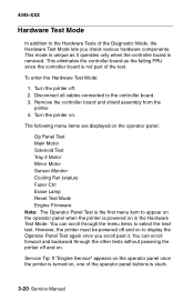
...Test Tray 2 Motor Mirror Motor Sensor Monitor Cooling Fan (status) Fuser Ctrl Erase Lamp Reset Test Mode Engine Firmware Note: The Operator Panel Test is the first menu item to appear on the operator panel when the printer is powered on , one of the operator panel buttons is ...turned on in the Hardware Test Mode. Remove the controller board and shield assembly from the printer. 4. Service Tip: If "Engine Service" appears on the operator panel once the printer is stuck. 3-20 Service Manual This eliminates the controller board as it . To enter the Hardware...
...Test Tray 2 Motor Mirror Motor Sensor Monitor Cooling Fan (status) Fuser Ctrl Erase Lamp Reset Test Mode Engine Firmware Note: The Operator Panel Test is the first menu item to appear on the operator panel when the printer is powered on , one of the operator panel buttons is ...turned on in the Hardware Test Mode. Remove the controller board and shield assembly from the printer. 4. Service Tip: If "Engine Service" appears on the operator panel once the printer is stuck. 3-20 Service Manual This eliminates the controller board as it . To enter the Hardware...
Service Manual
Page 101
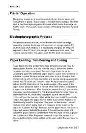
... is detected. If the exit sensor does not detect the paper within the toner cartridge assembly, creates the image to the fuser where the toner is detected. When the printer receives a printing command, the main drive motor turns on the paper as it was picked, a paper jam is drawn from the PC drum... charged, an image is exposed to the PC drum, the image is developed with toner, the toner is transferred to the paper. 4045-XXX Printer Operation The printer makes an image by applying toner dots to the main exit bin or the rear exit (if the rear door is the Electrophotographic Process...
... is detected. If the exit sensor does not detect the paper within the toner cartridge assembly, creates the image to the fuser where the toner is detected. When the printer receives a printing command, the main drive motor turns on the paper as it was picked, a paper jam is drawn from the PC drum... charged, an image is exposed to the PC drum, the image is developed with toner, the toner is transferred to the paper. 4045-XXX Printer Operation The printer makes an image by applying toner dots to the main exit bin or the rear exit (if the rear door is the Electrophotographic Process...

Service Manual
Page 119
Disconnect the two LVPS wires (A) from the inner air duct cover and remove the cover. Remove the redrive assembly. 4. Remove the screw from the fuser. 3. Repair Information 4-15 4045-XXX Fuser 1. Remove the right side cover. 2.
Disconnect the two LVPS wires (A) from the inner air duct cover and remove the cover. Remove the redrive assembly. 4. Remove the screw from the fuser. 3. Repair Information 4-15 4045-XXX Fuser 1. Remove the right side cover. 2.

Service Manual
Page 151
... 12G0441 12G0424 12G1860 12G0262 12G0255 12G0269 Units 1 1 1 1 1 1 1 2 6 1 2 10 2 1 1 1 4 1 1 1 1 1 1 1 1 1 1 1 1 1 Description Cover, Exit Duct, Fuser Cooling Air Support, Paper Bail Assembly, Optional Cover, Top Cover, Rear Link, Right Hinge Link, Spring Screw, M4x8 PP 12G0445 Cover, Right Side Pin, Hinge Screw, M3x8 PP 12G0445... Clip, PP 12G0445 Hinge, Right Cover, Upper Front M410 Cover, Upper Front M412 Screw w/washer, ...
... 12G0441 12G0424 12G1860 12G0262 12G0255 12G0269 Units 1 1 1 1 1 1 1 2 6 1 2 10 2 1 1 1 4 1 1 1 1 1 1 1 1 1 1 1 1 1 Description Cover, Exit Duct, Fuser Cooling Air Support, Paper Bail Assembly, Optional Cover, Top Cover, Rear Link, Right Hinge Link, Spring Screw, M4x8 PP 12G0445 Cover, Right Side Pin, Hinge Screw, M3x8 PP 12G0445... Clip, PP 12G0445 Hinge, Right Cover, Upper Front M410 Cover, Upper Front M412 Screw w/washer, ...

Service Manual
Page 168
4045-XXX Assembly 9: Fuser 6-20 Service Manual
4045-XXX Assembly 9: Fuser 6-20 Service Manual

Service Manual
Page 170
4045-XXX Assembly 9: Fuser (continued) 6-22 Service Manual
4045-XXX Assembly 9: Fuser (continued) 6-22 Service Manual
Service Manual
Page 189
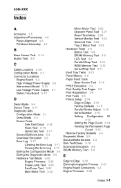
4045-XXX Index A Acronyms 1-5 Adjustment Procedures 4-2 Paper Alignment 4-3 Printhead Assembly 4-2 B Base Sensor Test 3-14 Button Test 3-9 C Cable Locations 3-29... Exiting the Diagnostic Mode 3-5 Hardware Test Mode 3-20 Engine Firmware 3-26 Erase Lamp Test 3-26 Fan/Fuser Test 3-25 Main Motor Test 3-22 Mirror Motor Test 3-23 Operator Panel Test 3-21 Reset Test Mode...Feed Tests Base Sensor Test 3-14 PPDS Emulation 3-3 Print Quality Test Pages 3-2 Print Registration 3-6 Print Tests 3-6 Printer Setup 3-14 Edge to Edge 3-16 Factory Defaults 3-16 Parallel Strobe Adjust 3-16 Serial Number 3-16 Setting ...
4045-XXX Index A Acronyms 1-5 Adjustment Procedures 4-2 Paper Alignment 4-3 Printhead Assembly 4-2 B Base Sensor Test 3-14 Button Test 3-9 C Cable Locations 3-29... Exiting the Diagnostic Mode 3-5 Hardware Test Mode 3-20 Engine Firmware 3-26 Erase Lamp Test 3-26 Fan/Fuser Test 3-25 Main Motor Test 3-22 Mirror Motor Test 3-23 Operator Panel Test 3-21 Reset Test Mode...Feed Tests Base Sensor Test 3-14 PPDS Emulation 3-3 Print Quality Test Pages 3-2 Print Registration 3-6 Print Tests 3-6 Printer Setup 3-14 Edge to Edge 3-16 Factory Defaults 3-16 Parallel Strobe Adjust 3-16 Serial Number 3-16 Setting ...

Service Manual
Page 190
...Messages 2-9 Error Log 3-17 ESD-sensitive Parts 4-1 Exiting the Configuration Mode 3-5 Exiting the Diagnostic Mode 3-5 F Factory Defaults 3-16 Fan/Fuser Test 3-25 Flash Test 3-19 H Handling ESD-sensitive Parts 4-1 Hardware Test Mode 3-20 How To Use This Parts Catalog 6-1 HVPS... Print Tests 3-6 Printer Operation 3-27 Printer Setup 3-14 Q Quick Disk Test 3-17 R Removals Charge Roller 4-8 Controller Board 4-9 Cooling Fan 4-11 Covers 4-4 Developer Drive Assembly Engine Board 4-14 Fuser 4-15 HVPS 4-17 4-13 I Input Tray Tests 3-13 Interconnect Board Connectors 5-10 L Laser Notice vii LCD Test...
...Messages 2-9 Error Log 3-17 ESD-sensitive Parts 4-1 Exiting the Configuration Mode 3-5 Exiting the Diagnostic Mode 3-5 F Factory Defaults 3-16 Fan/Fuser Test 3-25 Flash Test 3-19 H Handling ESD-sensitive Parts 4-1 Hardware Test Mode 3-20 How To Use This Parts Catalog 6-1 HVPS... Print Tests 3-6 Printer Operation 3-27 Printer Setup 3-14 Q Quick Disk Test 3-17 R Removals Charge Roller 4-8 Controller Board 4-9 Cooling Fan 4-11 Covers 4-4 Developer Drive Assembly Engine Board 4-14 Fuser 4-15 HVPS 4-17 4-13 I Input Tray Tests 3-13 Interconnect Board Connectors 5-10 L Laser Notice vii LCD Test...

Service Manual
Page 191
4045-XXX Inner Deflector 4-18 Left Side Frame 4-20 LVPS 4-21 Main Drive Assembly 4-23 Multipurpose Tray 4-24 Paper Alignment Assembly 4-25 Pick Roll 4-27 Printhead 4-28 Redrive Assembly 4-29 Right Side Frame 4-30 Transfer Roller 4-30 Reset Test Mode 3-26 Restore Factory Defaults 3-4 ROM Memory Test 3-10 S Safety ...Number 3-16 Serial Wrap Test 3-11 Service Checks Charge Roll 2-17 Cover Open Switch/Cable 2-19 Dead Machine 2-20 Erase Lamp 2-22 Fan 2-23 Fuser 2-23 Input Sensor 2-25 Input Tray(s) Option 2-26 Main Drive 2-29 Operator Panel 2-30 Options 2-32 Paper Feed 2-33 Parallel Port 2-35 Print...
4045-XXX Inner Deflector 4-18 Left Side Frame 4-20 LVPS 4-21 Main Drive Assembly 4-23 Multipurpose Tray 4-24 Paper Alignment Assembly 4-25 Pick Roll 4-27 Printhead 4-28 Redrive Assembly 4-29 Right Side Frame 4-30 Transfer Roller 4-30 Reset Test Mode 3-26 Restore Factory Defaults 3-4 ROM Memory Test 3-10 S Safety ...Number 3-16 Serial Wrap Test 3-11 Service Checks Charge Roll 2-17 Cover Open Switch/Cable 2-19 Dead Machine 2-20 Erase Lamp 2-22 Fan 2-23 Fuser 2-23 Input Sensor 2-25 Input Tray(s) Option 2-26 Main Drive 2-29 Operator Panel 2-30 Options 2-32 Paper Feed 2-33 Parallel Port 2-35 Print...


