Service Manual
Page 4
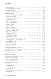
... 3-6 Hardware Tests 3-8 Input Tray Tests 3-13 Base Sensor Test 3-14 Printer Setup 3-14 Error Log 3-17 Device Tests 3-17 Hardware Test Mode 3-...Printer Operation 3-27 Electrophotographic Process 3-27 Paper Feeding, Transferring and Fusing 3-27 Paper Path/Sensor Locations 3-28 Cable Locations 3-29 Repair Information 4-1 Handling ESD-Sensitive Parts 4-1 Adjustment Procedures 4-2 Printhead Assembly 4-2 Paper Alignment 4-3 Removal Procedures 4-4 Covers 4-4 Charge Roller 4-8 Controller Board 4-9 Cooling Fan 4-11 Developer Drive Assembly 4-13 Engine Board 4-14 iv Service Manual
... 3-6 Hardware Tests 3-8 Input Tray Tests 3-13 Base Sensor Test 3-14 Printer Setup 3-14 Error Log 3-17 Device Tests 3-17 Hardware Test Mode 3-...Printer Operation 3-27 Electrophotographic Process 3-27 Paper Feeding, Transferring and Fusing 3-27 Paper Path/Sensor Locations 3-28 Cable Locations 3-29 Repair Information 4-1 Handling ESD-Sensitive Parts 4-1 Adjustment Procedures 4-2 Printhead Assembly 4-2 Paper Alignment 4-3 Removal Procedures 4-4 Covers 4-4 Charge Roller 4-8 Controller Board 4-9 Cooling Fan 4-11 Developer Drive Assembly 4-13 Engine Board 4-14 iv Service Manual

Service Manual
Page 14
4045-XXX Japanese Laser Notice Chinese Laser Notice xiv Service Manual
4045-XXX Japanese Laser Notice Chinese Laser Notice xiv Service Manual

Service Manual
Page 20
4045-XXX xx Service Manual
4045-XXX xx Service Manual

Service Manual
Page 22
Some options are available. Contact your country. 500-Sheet Drawer SDRAM Memory DIMMs: 4MB, 8MB, 16MB, 32MB and 64MB Flash Memory DIMMs: 2MB, 4MB, 8MB and 16MB Internal Network Options Token Ring Ethernet 10/100BaseTX 10Base2/T Tri-Port Card Hard Disk - 2.1GB Coax/Twinax Adapter for options available in every country. 4045-XXX Options The following options are not available in your point of purchase for SCS External Network Adapter: Marknet Pro 1 and 3 series compatible 1-2 Service Manual
Some options are available. Contact your country. 500-Sheet Drawer SDRAM Memory DIMMs: 4MB, 8MB, 16MB, 32MB and 64MB Flash Memory DIMMs: 2MB, 4MB, 8MB and 16MB Internal Network Options Token Ring Ethernet 10/100BaseTX 10Base2/T Tri-Port Card Hard Disk - 2.1GB Coax/Twinax Adapter for options available in every country. 4045-XXX Options The following options are not available in your point of purchase for SCS External Network Adapter: Marknet Pro 1 and 3 series compatible 1-2 Service Manual
Service Manual
Page 24
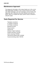
... Spring hook Analog or digital multimeter Parallel wrap plug 1319128 Serial wrap plug 1329048 Twinax/serial debug cable 1381963 Coax/serial debug cable 1381964 1-4 Service Manual 4045-XXX Maintenance Approach The diagnostic information in this manual leads you complete the repair, perform tests as needed to determine the printer problem and repair the failure.
... Spring hook Analog or digital multimeter Parallel wrap plug 1319128 Serial wrap plug 1329048 Twinax/serial debug cable 1381963 Coax/serial debug cable 1381964 1-4 Service Manual 4045-XXX Maintenance Approach The diagnostic information in this manual leads you complete the repair, perform tests as needed to determine the printer problem and repair the failure.

Service Manual
Page 26
4045-XXX 1-6 Service Manual
4045-XXX 1-6 Service Manual
Service Manual
Page 28
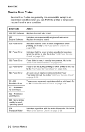
... Error Fuser is too hot during printing or when printer is below temperature when printing. Go to temporarily recover from the error condition. Go to the Transport Motor "Main Drive Service Check" on page 2-36. 931 - Go to the "Printhead Service Check" on page 2-29. 2-2 Service Manual Engine Software Replace the engine board. 920 Fuser...
... Error Fuser is too hot during printing or when printer is below temperature when printing. Go to temporarily recover from the error condition. Go to the Transport Motor "Main Drive Service Check" on page 2-36. 931 - Go to the "Printhead Service Check" on page 2-29. 2-2 Service Manual Engine Software Replace the engine board. 920 Fuser...

Service Manual
Page 30
.... 964 Emulation Error 965 Emulation Error 975 - 979 Network Card Replace the SIMM in Slot 1. Unrecognizable Network Card. Flash parts failed while programming Network Card. 2-4 Service Manual The following errors indicate a failure with the network card. 975 -
.... 964 Emulation Error 965 Emulation Error 975 - 979 Network Card Replace the SIMM in Slot 1. Unrecognizable Network Card. Flash parts failed while programming Network Card. 2-4 Service Manual The following errors indicate a failure with the network card. 975 -

Service Manual
Page 32
... Printing Directory List Status Action The printer is processing or printing a list of the display. No more data is processed, but the printer processes all paper currently in the paper path. Press Go to return to reset the printer. 2-6 Service Manual Press Select to Ready after the ...page prints. No more data is processed, but the printer processes all paper currently in the printer paper path. Press Stop to take the printer out of Ready. Press Stop to take...
... Printing Directory List Status Action The printer is processing or printing a list of the display. No more data is processed, but the printer processes all paper currently in the paper path. Press Go to return to reset the printer. 2-6 Service Manual Press Select to Ready after the ...page prints. No more data is processed, but the printer processes all paper currently in the printer paper path. Press Stop to take the printer out of Ready. Press Stop to take...

Service Manual
Page 34
This occurs when Menu> or The printer menus have been disabled. No button actions are being programmed, which means fonts or macros are possible while this message is displayed. 4045-XXX User Status Message Programming Disk (Do Not Power Off) Menus Disabled Activating Menu Changes Status Action The disk is being written to disk at the same time, the Program Flash message is displayed. Note: If information is written to flash memory and to disk.
This occurs when Menu> or The printer menus have been disabled. No button actions are being programmed, which means fonts or macros are possible while this message is displayed. 4045-XXX User Status Message Programming Disk (Do Not Power Off) Menus Disabled Activating Menu Changes Status Action The disk is being written to disk at the same time, the Program Flash message is displayed. Note: If information is written to flash memory and to disk.

Service Manual
Page 36
...a defective disk. Once this message is displayed: Press Go to flash. 53 Unformatted Flash This message is displayed when the printer detects an unformatted flash at power on . The flash is marked as bad and normal operation continues. The following actions may...setting, but no communication can exist with a defective disk. The Format Disk menu is marked defective and normal printer operations continue. The disk is not shown. 2-10 Service Manual Disk operations are not allowed until the network software is reloaded. 56 Parallel Port Disabled This error is displayed...
...a defective disk. Once this message is displayed: Press Go to flash. 53 Unformatted Flash This message is displayed when the printer detects an unformatted flash at power on . The flash is marked as bad and normal operation continues. The following actions may...setting, but no communication can exist with a defective disk. The Format Disk menu is marked defective and normal printer operations continue. The disk is not shown. 2-10 Service Manual Disk operations are not allowed until the network software is reloaded. 56 Parallel Port Disabled This error is displayed...
Service Manual
Page 38
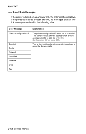
... Go to process any link, no messages display. The link messages are listed in the following table. This is the host interface from which the printer is locked on page 3-15. This condition can only be cleared when a valid configuration ID is set or is not set . User Message Explanation... Check Configuration ID Parallel Serial Network LocalTalk Infrared USB Fax The printer configuration ID is invalid. 4045-XXX User Line 2 Link Messages If the printer is currently drawing data. 2-12 Service Manual
... Go to process any link, no messages display. The link messages are listed in the following table. This is the host interface from which the printer is locked on page 3-15. This condition can only be cleared when a valid configuration ID is set or is not set . User Message Explanation... Check Configuration ID Parallel Serial Network LocalTalk Infrared USB Fax The printer configuration ID is invalid. 4045-XXX User Line 2 Link Messages If the printer is currently drawing data. 2-12 Service Manual

Service Manual
Page 40
... turn . 11. The LED comes on . 12. The printhead mirror motor turns on . 2. The LED stays on solid and the operator panel displays "Ready". 2-14 Service Manual The fuser takes longer to warm up from a cold start than a warm start. 7. The exit rollers turn the printer On, it performs a Power-On Self Test.
... turn . 11. The LED comes on . 12. The printhead mirror motor turns on . 2. The LED stays on solid and the operator panel displays "Ready". 2-14 Service Manual The fuser takes longer to warm up from a cold start than a warm start. 7. The exit rollers turn the printer On, it performs a Power-On Self Test.

Service Manual
Page 42
Print quality - Action Go to "Print Quality - Paper feed problem with 500 sheet paper tray option. Toner on edge of printed page. Vertical black bands on backside of copy. Toner on backside of the page" on page 2-47. Go to "Print Quality - Black bands on outer edges of printed page" on page 2-44. Go to "Input Tray(s) Option Service Check" on page 2-26. 2-16 Service Manual 4045-XXX Symptom Print quality -
Print quality - Action Go to "Print Quality - Paper feed problem with 500 sheet paper tray option. Toner on edge of printed page. Vertical black bands on backside of copy. Toner on backside of the page" on page 2-47. Go to "Print Quality - Black bands on outer edges of printed page" on page 2-44. Go to "Input Tray(s) Option Service Check" on page 2-26. 2-16 Service Manual 4045-XXX Symptom Print quality -

Service Manual
Page 44
Check for continuity from the bushing to the contact must be secure. 2-18 Service Manual If incorrect, replace the right charge roller arm. Excessive contamination could cause intermittent charging of wear or contamination. If incorrect, replace the bushing. Check the ...
Check for continuity from the bushing to the contact must be secure. 2-18 Service Manual If incorrect, replace the right charge roller arm. Excessive contamination could cause intermittent charging of wear or contamination. If incorrect, replace the bushing. Check the ...

Service Manual
Page 46
... present, go to step 9. If +24 V dc is blown. 2-20 Service Manual Remove the controller board. Observe all necessary ESD precautions when removing and handling the controller board, engine board or any signs of damage. Service Tip: The LVPS uses a self-docking connector that mates with another connector mounted...replace if necessary. Check for +5 V dc at the TP5 test point and +24 V dc at pin 7 of the tray 2 connector located under the printer. If the printer powers on the left side frame assembly. If incorrect, go to step 4. FRU 1 Line Voltage 2 AC Line Cord 3 +24 V dc at the...
... present, go to step 9. If +24 V dc is blown. 2-20 Service Manual Remove the controller board. Observe all necessary ESD precautions when removing and handling the controller board, engine board or any signs of damage. Service Tip: The LVPS uses a self-docking connector that mates with another connector mounted...replace if necessary. Check for +5 V dc at the TP5 test point and +24 V dc at pin 7 of the tray 2 connector located under the printer. If the printer powers on the left side frame assembly. If incorrect, go to step 4. FRU 1 Line Voltage 2 AC Line Cord 3 +24 V dc at the...
Service Manual
Page 48
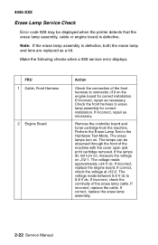
...from the machine. The erase lamps turn on, measure the voltage on . If correct, replace the erase lamp assembly. 2-22 Service Manual 4045-XXX Erase Lamp Service Check Error code 928 may be observed through the front of the machine with the cover open and print cartridge removed. Perform ...approximately +24 V dc. If incorrect, replace the engine board. Check the front harness to 0.8 V dc. The lamps can be displayed when the printer detects that the erase lamp assembly, cable or engine board is defective, both the erase lamp and lens are replaced as a kit. If incorrect, repair...
...from the machine. The erase lamps turn on, measure the voltage on . If correct, replace the erase lamp assembly. 2-22 Service Manual 4045-XXX Erase Lamp Service Check Error code 928 may be observed through the front of the machine with the cover open and print cartridge removed. Perform ...approximately +24 V dc. If incorrect, replace the engine board. Check the front harness to 0.8 V dc. The lamps can be displayed when the printer detects that the erase lamp assembly, cable or engine board is defective, both the erase lamp and lens are replaced as a kit. If incorrect, repair...
Service Manual
Page 50
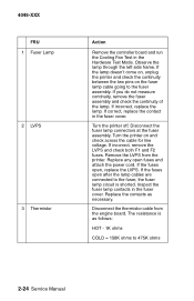
..., replace the contact in the Hardware Test Mode. If incorrect, replace the lamp. Inspect the fuser lamp contacts in the fuser cover. Turn the printer off. If incorrect, remove the LVPS and check both F1 and F2 fuses. Remove the LVPS from the engine board. Turn the... printer on the fuser lamp cable going to the fuser assembly. Observe the lamp through the left side frame. If the fuses open after the lamp cables are connected to 475K ohms 2-24 Service Manual Replace the contacts as follows: HOT - 1K ohms COLD...
..., replace the contact in the Hardware Test Mode. If incorrect, replace the lamp. Inspect the fuser lamp contacts in the fuser cover. Turn the printer off. If incorrect, remove the LVPS and check both F1 and F2 fuses. Remove the LVPS from the engine board. Turn the... printer on the fuser lamp cable going to the fuser assembly. Observe the lamp through the left side frame. If the fuses open after the lamp cables are connected to 475K ohms 2-24 Service Manual Replace the contacts as follows: HOT - 1K ohms COLD...

Service Manual
Page 52
...sources to make sure they are working properly. Run the Tray 2 Motor Test in the Hardware Test Mode with the controller board removed. 4045-XXX Service Tip: Run the Sensor Monitor Test in the Hardware Test Mode to verify motor and related paper feed components are properly feeding paper. If a ... Action Check the input sensor flag for approximately +5 V dc at J2-3 on , actuate the tray 2 solenoid from the Solenoid Test to feed paper. 2-26 Service Manual With the motor on the engine board. If correct, replace the input sensor assembly. If incorrect, replace the engine board.
...sources to make sure they are working properly. Run the Tray 2 Motor Test in the Hardware Test Mode with the controller board removed. 4045-XXX Service Tip: Run the Sensor Monitor Test in the Hardware Test Mode to verify motor and related paper feed components are properly feeding paper. If a ... Action Check the input sensor flag for approximately +5 V dc at J2-3 on , actuate the tray 2 solenoid from the Solenoid Test to feed paper. 2-26 Service Manual With the motor on the engine board. If correct, replace the input sensor assembly. If incorrect, replace the engine board.

Service Manual
Page 54
4045-XXX FRU 4 Tray 2 Motor Action Use the Tray 2 Motor Test to check the tray 2 motor. Replace as necessary. 2-28 Service Manual
4045-XXX FRU 4 Tray 2 Motor Action Use the Tray 2 Motor Test to check the tray 2 motor. Replace as necessary. 2-28 Service Manual


