User's Guide
Page 6
Check MP Feeder 192 9 Maintaining Your Printer 193 Ordering a Print Cartridge 193 Storing the Print Cartridge 194 Replacing the Print Cartridge 194 Cleaning the Printhead Lens 195 Ordering a Charge Roll Kit 195 vi Table of Contents Short Paper 190 250 Paper Jam - ...Material 143 Using the Multipurpose Feeder 149 Closing the Multipurpose Feeder 150 6 Understanding Printer Messages 151 Status Messages 151 Line 1 Messages 152 Warning Messages 158 Attendance Messages 159 7 Solving Printer Problems 173 Display Problems 175 Printing Problems 176 Print Quality Problems 178 Option ...
Check MP Feeder 192 9 Maintaining Your Printer 193 Ordering a Print Cartridge 193 Storing the Print Cartridge 194 Replacing the Print Cartridge 194 Cleaning the Printhead Lens 195 Ordering a Charge Roll Kit 195 vi Table of Contents Short Paper 190 250 Paper Jam - ...Material 143 Using the Multipurpose Feeder 149 Closing the Multipurpose Feeder 150 6 Understanding Printer Messages 151 Status Messages 151 Line 1 Messages 152 Warning Messages 158 Attendance Messages 159 7 Solving Printer Problems 173 Display Problems 175 Printing Problems 176 Print Quality Problems 178 Option ...
User's Guide
Page 191
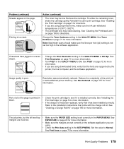
... Check the Print Area setting in the PAPER MENU. See Print Area on page 195 for more information. Remove the cartridge. See "Cleaning the Printhead Lens" on page 76 for more information. See Toner Darkness on page 71 for more information. • If you are using downloaded fonts,... users should make sure the ink can withstand temperatures of 200°C (392°F). • The printhead lens may be low. Part of all of the print job or add additional printer memory. Printing is poor. Refer to Normal. Characters have jagged or uneven edges. • Change the...
... Check the Print Area setting in the PAPER MENU. See Print Area on page 195 for more information. Remove the cartridge. See "Cleaning the Printhead Lens" on page 76 for more information. See Toner Darkness on page 71 for more information. • If you are using downloaded fonts,... users should make sure the ink can withstand temperatures of 200°C (392°F). • The printhead lens may be low. Part of all of the print job or add additional printer memory. Printing is poor. Refer to Normal. Characters have jagged or uneven edges. • Change the...
User's Guide
Page 207
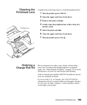
... page 178 for information about Lexmark Authorized Supplies Dealers in the kit. In other countries, contact the place where you 're in the U.S. Installation instructions are included in your printer. Cleaning the Printhead Lens 195 Cleaning the Printhead Lens Printhead Lens Complete the following steps to clean the printhead lens: 1 Turn the printer power Off (O). 2 Open the...
... page 178 for information about Lexmark Authorized Supplies Dealers in the kit. In other countries, contact the place where you 're in the U.S. Installation instructions are included in your printer. Cleaning the Printhead Lens 195 Cleaning the Printhead Lens Printhead Lens Complete the following steps to clean the printhead lens: 1 Turn the printer power Off (O). 2 Open the...
User's Guide
Page 298
...definition 234 black partial page 179 blank operator panel display 175 Blank Pages (Finishing Menu) 53 Buffered Jobs (Config Menu) 106 Busy, printer state 152 buttons, operator panel 35 C cable parallel, attaching 12 power, attaching 20 USB, attaching Macintosh 18 Windows 2000 14 Windows ... 286 Index CD contents x, 24 MarkVision 25, 26 online documentation x, 24 changing printer settings operator panel 40 software application 33 characters incorrect 181 jagged 179 charge roll kit, ordering 195 cleaning printhead lens 195 closing multipurpose feeder 150 rear output bin door 134 upper front door ...
...definition 234 black partial page 179 blank operator panel display 175 Blank Pages (Finishing Menu) 53 Buffered Jobs (Config Menu) 106 Busy, printer state 152 buttons, operator panel 35 C cable parallel, attaching 12 power, attaching 20 USB, attaching Macintosh 18 Windows 2000 14 Windows ... 286 Index CD contents x, 24 MarkVision 25, 26 online documentation x, 24 changing printer settings operator panel 40 software application 33 characters incorrect 181 jagged 179 charge roll kit, ordering 195 cleaning printhead lens 195 closing multipurpose feeder 150 rear output bin door 134 upper front door ...
User's Guide
Page 307
...1 warning messages See warning messages Printer Language (Setup Menu) 73 printer memory option 206 installing 207 removing 210 printer messages attendance See attendance messages service See service messages status See status messages warning messages See warning messages printer settings current default 39 operator panel ... 5 items 1 loading standard input tray 6 removing packaging 2 unpacking 1 utility 24 printer states Busy 152 Not Ready 154 Power Saver 154 Ready 156 Ready Hex 156 Waiting 157 printhead lens, cleaning 195 printing contents flash memory option 57 hard disk option 57 font sample...
...1 warning messages See warning messages Printer Language (Setup Menu) 73 printer memory option 206 installing 207 removing 210 printer messages attendance See attendance messages service See service messages status See status messages warning messages See warning messages printer settings current default 39 operator panel ... 5 items 1 loading standard input tray 6 removing packaging 2 unpacking 1 utility 24 printer states Busy 152 Not Ready 154 Power Saver 154 Ready 156 Ready Hex 156 Waiting 157 printhead lens, cleaning 195 printing contents flash memory option 57 hard disk option 57 font sample...
Service Manual
Page 3
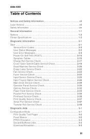
4045-XXX Table of Contents Notices and Safety Information vii Laser Notices vii Safety Information xv General Information 1-1 Options 1-2 Printer Specifications 1-3 Diagnostic Information 2-1 Start 2-1 Service Error Codes 2-2 User Status Messages 2-5 User Error Messages 2-9 Power-On Self Test...Check 2-29 Operator Panel Service Check 2-30 Options Service Check 2-32 Paper Feed Service Check 2-33 Parallel Port Service Check 2-35 Printhead Service Check 2-36 Print Quality Service Check 2-37 Serial Port Service Check 2-47 Transfer Roll Service Check 2-48 Diagnostic Aids 3-1 ...
4045-XXX Table of Contents Notices and Safety Information vii Laser Notices vii Safety Information xv General Information 1-1 Options 1-2 Printer Specifications 1-3 Diagnostic Information 2-1 Start 2-1 Service Error Codes 2-2 User Status Messages 2-5 User Error Messages 2-9 Power-On Self Test...Check 2-29 Operator Panel Service Check 2-30 Options Service Check 2-32 Paper Feed Service Check 2-33 Parallel Port Service Check 2-35 Printhead Service Check 2-36 Print Quality Service Check 2-37 Serial Port Service Check 2-47 Transfer Roll Service Check 2-48 Diagnostic Aids 3-1 ...
Service Manual
Page 4
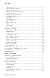
...Diagnostic Mode 3-5 Exiting the Diagnostic Mode 3-5 Print Registration 3-6 Print Tests 3-6 Hardware Tests 3-8 Input Tray Tests 3-13 Base Sensor Test 3-14 Printer Setup 3-14 Error Log 3-17 Device Tests 3-17 Hardware Test Mode 3-20 Operator Panel Test 3-21 Main Motor Test 3-22 Solenoid Test 3-...Monitor Test 3-24 Cooling Fan / Fuser Control Test 3-25 Erase Lamp Test 3-26 Reset Test Mode 3-26 Engine Firmware 3-26 Printer Operation 3-27 Electrophotographic Process 3-27 Paper Feeding, Transferring and Fusing 3-27 Paper Path/Sensor Locations 3-28 Cable Locations 3-29 Repair ...
...Diagnostic Mode 3-5 Exiting the Diagnostic Mode 3-5 Print Registration 3-6 Print Tests 3-6 Hardware Tests 3-8 Input Tray Tests 3-13 Base Sensor Test 3-14 Printer Setup 3-14 Error Log 3-17 Device Tests 3-17 Hardware Test Mode 3-20 Operator Panel Test 3-21 Main Motor Test 3-22 Solenoid Test 3-...Monitor Test 3-24 Cooling Fan / Fuser Control Test 3-25 Erase Lamp Test 3-26 Reset Test Mode 3-26 Engine Firmware 3-26 Printer Operation 3-27 Electrophotographic Process 3-27 Paper Feeding, Transferring and Fusing 3-27 Paper Path/Sensor Locations 3-28 Cable Locations 3-29 Repair ...
Service Manual
Page 5
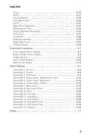
...Side Frame 4-20 LVPS 4-21 Main Drive Assembly 4-23 Multipurpose Tray 4-24 Paper Alignment Assembly 4-25 Pick Roll 4-27 Printhead 4-28 Redrive Assembly 4-29 Right Side Frame 4-30 Transfer Roller 4-30 Connector Locations 5-1 Low Voltage Power Supply 5-1 High...Voltage Power Supply 5-2 Engine Board 5-4 Interconnect Board 5-10 Option Tray Board 5-12 Parts Catalog 6-1 Assembly 1: Covers 6-2 Assembly 2: Frame 6-6 Assembly 3: Printhead 6-8 Assembly 4: Paper Feed - Output 6-14 Assembly 7: Main Drive 6-16 Assembly 8: Developer Drive 6-18 Assembly 9: Fuser 6-20 Assembly 10: Transfer...
...Side Frame 4-20 LVPS 4-21 Main Drive Assembly 4-23 Multipurpose Tray 4-24 Paper Alignment Assembly 4-25 Pick Roll 4-27 Printhead 4-28 Redrive Assembly 4-29 Right Side Frame 4-30 Transfer Roller 4-30 Connector Locations 5-1 Low Voltage Power Supply 5-1 High...Voltage Power Supply 5-2 Engine Board 5-4 Interconnect Board 5-10 Option Tray Board 5-12 Parts Catalog 6-1 Assembly 1: Covers 6-2 Assembly 2: Frame 6-6 Assembly 3: Printhead 6-8 Assembly 4: Paper Feed - Output 6-14 Assembly 7: Main Drive 6-16 Assembly 8: Developer Drive 6-18 Assembly 9: Fuser 6-20 Assembly 10: Transfer...
Service Manual
Page 28
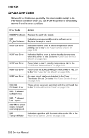
...that the fuser is below standby temperature when the printer is below temperature when printing. Go to reach operating speed. 936 Indicates a problem with the printhead. Go to the "Hot Fuser Service Check" on page 2-29. 2-2 Service Manual Printhead: Lost Hsyncs 935 - Go to the "Hot ...page 2-23. 923 Fuser Error Fuser is too hot during printing or when printer is idle. Error Code Action 900 RIP Software Replace the controller board. 902 Indicates an unrecoverable engine software error. Printhead: no first Hsync 932 - Go to temporarily recover from the error condition....
...that the fuser is below standby temperature when the printer is below temperature when printing. Go to reach operating speed. 936 Indicates a problem with the printhead. Go to the "Hot Fuser Service Check" on page 2-29. 2-2 Service Manual Printhead: Lost Hsyncs 935 - Go to the "Hot ...page 2-23. 923 Fuser Error Fuser is too hot during printing or when printer is idle. Error Code Action 900 RIP Software Replace the controller board. 902 Indicates an unrecoverable engine software error. Printhead: no first Hsync 932 - Go to temporarily recover from the error condition....

Service Manual
Page 40
... POST functioning of pels, and then clears. 3. "Performing Self Test" appears on the display. 6. The exit rollers turn the printer On, it performs a Power-On Self Test. The printhead mirror motor turns off . 14. The operator panel displays one and a half rows of diamonds, and then clears. 4. "Ready... . 11. The developer drive assembly drives the developer shaft in the toner cartridge. 10. The main drive motor turns off . 16. The printhead mirror motor turns on solid and the operator panel displays "Ready". 2-14 Service Manual The LED comes on . 9. The operator panel displays one...
... POST functioning of pels, and then clears. 3. "Performing Self Test" appears on the display. 6. The exit rollers turn the printer On, it performs a Power-On Self Test. The printhead mirror motor turns off . 14. The operator panel displays one and a half rows of diamonds, and then clears. 4. "Ready... . 11. The developer drive assembly drives the developer shaft in the toner cartridge. 10. The main drive motor turns off . 16. The printhead mirror motor turns on solid and the operator panel displays "Ready". 2-14 Service Manual The LED comes on . 9. The operator panel displays one...

Service Manual
Page 62
... at J8-5 measures approximately +24 V dc. These error codes indicate a problem with the mirror motor circuit in the printhead assembly or the mirror motor cable to the printhead. If incorrect, replace the defective cable. If incorrect, replace the cable. The voltage at J5-6 measures approximately +5 V... dc. Check the continuity of the mirror motor cable connected to J5 on the engine board. If correct, replace the printhead assembly. Service Error Code 1 Error Code 931 No first HYSNC Signal Error Code 932 Lost HYSNC 2 Error Code 935 Mirror Motor unable ...
... at J8-5 measures approximately +24 V dc. These error codes indicate a problem with the mirror motor circuit in the printhead assembly or the mirror motor cable to the printhead. If incorrect, replace the defective cable. If incorrect, replace the cable. The voltage at J5-6 measures approximately +5 V... dc. Check the continuity of the mirror motor cable connected to J5 on the engine board. If correct, replace the printhead assembly. Service Error Code 1 Error Code 931 No first HYSNC Signal Error Code 932 Lost HYSNC 2 Error Code 935 Mirror Motor unable ...

Service Manual
Page 65
... Contact 4 HVPS/HVPS Cable/ Engine Board 5 Printhead Assembly Action Check the contacts on the photoconductor. The printer is posted if the printhead assembly fails and the printer does not give a blank copy symptom. Symptom ...1 Random Marks Action Check the print cartridge for damage, cartridge contact wear or contamination. If the contacts are stuck to the photoconductor, charge roll or transfer roll. Diagnostic Information 2-39 The printhead used in the printer does not have a mechanical shutter as previous laser printers...
... Contact 4 HVPS/HVPS Cable/ Engine Board 5 Printhead Assembly Action Check the contacts on the photoconductor. The printer is posted if the printhead assembly fails and the printer does not give a blank copy symptom. Symptom ...1 Random Marks Action Check the print cartridge for damage, cartridge contact wear or contamination. If the contacts are stuck to the photoconductor, charge roll or transfer roll. Diagnostic Information 2-39 The printhead used in the printer does not have a mechanical shutter as previous laser printers...

Service Manual
Page 69
...same procedure as outlined in the "Erase Lamp Test" on the Optra M410 printers cannot be cleaned. Check the high voltage contact from the HVPS...found , clean the ends of contamination, pitting or a loose cable to correct a background problem. The printhead on page 3-26. Diagnostic Information 2-43 Check the high voltage contacts on the ends of the shaft that... of the shaft or replace the transfer roll assembly. 4045-XXX FRU 1 Erase Lamp/Lens Assembly 2 Printhead 3 Transfer Roll Assembly 4 High Voltage Contacts Action Check the erase lamp lens for any problems are clean...
...same procedure as outlined in the "Erase Lamp Test" on the Optra M410 printers cannot be cleaned. Check the high voltage contact from the HVPS...found , clean the ends of contamination, pitting or a loose cable to correct a background problem. The printhead on page 3-26. Diagnostic Information 2-43 Check the high voltage contacts on the ends of the shaft that... of the shaft or replace the transfer roll assembly. 4045-XXX FRU 1 Erase Lamp/Lens Assembly 2 Printhead 3 Transfer Roll Assembly 4 High Voltage Contacts Action Check the erase lamp lens for any problems are clean...
Service Manual
Page 97
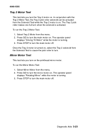
... full turn when the solenoid is turning. 3. Once the Tray 2 motor is turning. 3. Diagnostic Aids 3-23 Press GO to turn the main motor on the printhead mirror motor. The operator panel displays "Rotating Mirror" while the motor is turned on . Press GO to turn the main motor off . To run the...
... full turn when the solenoid is turning. 3. Once the Tray 2 motor is turning. 3. Diagnostic Aids 3-23 Press GO to turn the main motor on the printhead mirror motor. The operator panel displays "Rotating Mirror" while the motor is turned on . Press GO to turn the main motor off . To run the...

Service Manual
Page 106
... Self Test" displays. 4. Print a Print Test page and check for skew adjustment, page count setting, printer serial number code levels and print registration settings. 5. Loosen the three printhead mounting screws. Turn the printer off. 2. d. 4045-XXX Adjustment Procedures Printhead Assembly This adjustment must be printed on letter or A4 paper from Tray 1. Press and...
... Self Test" displays. 4. Print a Print Test page and check for skew adjustment, page count setting, printer serial number code levels and print registration settings. 5. Loosen the three printhead mounting screws. Turn the printer off. 2. d. 4045-XXX Adjustment Procedures Printhead Assembly This adjustment must be printed on letter or A4 paper from Tray 1. Press and...

Service Manual
Page 120
Remove the four fuser mounting screws (B) and slide the fuser out of the printer. 4-16 Service Manual 4045-XXX 5. Disconnect the thermistor from the printhead/mirror motor cable. 6.
Remove the four fuser mounting screws (B) and slide the fuser out of the printer. 4-16 Service Manual 4045-XXX 5. Disconnect the thermistor from the printhead/mirror motor cable. 6.

Service Manual
Page 132
Remove the top cover. 2. Note: Go to the "Adjustment Procedures" on page 4-2 and perform the printhead assembly adjustment whenever the printhead is removed or the printhead mounting screws are loosened. 4-28 Service Manual 4045-XXX Printhead 1. Remove the three printhead mounting screws (A) and remove the printhead. Disconnect the two printhead cables from the printhead assembly. 3.
Remove the top cover. 2. Note: Go to the "Adjustment Procedures" on page 4-2 and perform the printhead assembly adjustment whenever the printhead is removed or the printhead mounting screws are loosened. 4-28 Service Manual 4045-XXX Printhead 1. Remove the three printhead mounting screws (A) and remove the printhead. Disconnect the two printhead cables from the printhead assembly. 3.

Service Manual
Page 139
J4 Cover Open Switch 1 2 3 4 5 6 7 8 J5 Printhead 1 2 3 4 5 6 7 J6 RS232C Interface X J7 Paper Output Sensor 1 Exit Tray O/C Sensor 2 3 4 5 6 Signal Not Used Not Used Not Used Not Used Not Used +5 V dc Cover Open Switch Ground Adjust LD Enable Video Ground Ground +5 V dc HSYNC Not Used Paper Out Sensor Ground LED Drive Exit OC Sensor Ground LED Drive Connector Locations 5-5 4045-XXX Connector Pin No.
J4 Cover Open Switch 1 2 3 4 5 6 7 8 J5 Printhead 1 2 3 4 5 6 7 J6 RS232C Interface X J7 Paper Output Sensor 1 Exit Tray O/C Sensor 2 3 4 5 6 Signal Not Used Not Used Not Used Not Used Not Used +5 V dc Cover Open Switch Ground Adjust LD Enable Video Ground Ground +5 V dc HSYNC Not Used Paper Out Sensor Ground LED Drive Exit OC Sensor Ground LED Drive Connector Locations 5-5 4045-XXX Connector Pin No.

Service Manual
Page 156
4045-XXX Assembly 3: Printhead 6-8 Service Manual
4045-XXX Assembly 3: Printhead 6-8 Service Manual

Service Manual
Page 157
4045-XXX AsmIndex 3-1 3-2 3-3 3-3 Part Number 12G0298 12G3551 Units 3 2 1 1 Description Screw, M4x12 PP 12G0445 Washer, PP 12G0445 Printhead, Complete M410 Printhead, Complete M412 Parts Catalog 6-9
4045-XXX AsmIndex 3-1 3-2 3-3 3-3 Part Number 12G0298 12G3551 Units 3 2 1 1 Description Screw, M4x12 PP 12G0445 Washer, PP 12G0445 Printhead, Complete M410 Printhead, Complete M412 Parts Catalog 6-9


