Quick Start Guide
Page 5
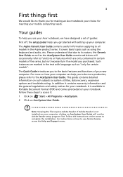
... as system utilities, data recovery, expansion options and troubleshooting. Note: Viewing the file requires Adobe Reader. The Aspire Generic User Guide contains useful information applying to all models in Portable Document Format (PDF) and comes preloaded on the screen to complete the installation. Follow the instructions on your notebook. This guide contains detailed information on such subjects as using the keyboard and audio, etc. Follow these steps to access it contains...
... as system utilities, data recovery, expansion options and troubleshooting. Note: Viewing the file requires Adobe Reader. The Aspire Generic User Guide contains useful information applying to all models in Portable Document Format (PDF) and comes preloaded on the screen to complete the installation. Follow the instructions on your notebook. This guide contains detailed information on such subjects as using the keyboard and audio, etc. Follow these steps to access it contains...
Quick Start Guide
Page 7
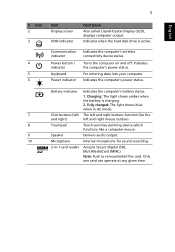
... in -1 card reader Indicates the computer's battery status. 1. Note: Push to remove/install the card. Indicates the computer's power status. Accepts Secure Digital (SD), MultiMediaCard (MMC). Indicates when the hard disk drive is charging. 2. For entering data into your computer. The left and right buttons function like a computer mouse. Touch-sensitive pointing device which functions like the left and right) Touchpad Speaker Microphone 2-in AC mode. Only one card can operate at any given time. Turns the...
... in -1 card reader Indicates the computer's battery status. 1. Note: Push to remove/install the card. Indicates the computer's power status. Accepts Secure Digital (SD), MultiMediaCard (MMC). Indicates when the hard disk drive is charging. 2. For entering data into your computer. The left and right buttons function like a computer mouse. Touch-sensitive pointing device which functions like the left and right) Touchpad Speaker Microphone 2-in AC mode. Only one card can operate at any given time. Turns the...
Quick Start Guide
Page 8
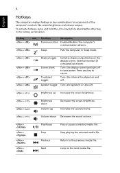
... media file. Increases the sound volume. + < > Volume down Volume up Decreases the screen brightness. To activate hotkeys, press and hold the key before pressing the other key in Sleep mode. + + + + Display toggle Screen blank Touchpad toggle Switches display output between the display screen, external monitor (if connected) and both. Turns the display screen backlight off to the previous media file. Return to save power. Jump to return. Turns the internal touchpad on and off . Hotkey Icon + + Function Description Communication Enables/disables...
... media file. Increases the sound volume. + < > Volume down Volume up Decreases the screen brightness. To activate hotkeys, press and hold the key before pressing the other key in Sleep mode. + + + + Display toggle Screen blank Touchpad toggle Switches display output between the display screen, external monitor (if connected) and both. Turns the display screen backlight off to the previous media file. Return to save power. Jump to return. Turns the internal touchpad on and off . Hotkey Icon + + Function Description Communication Enables/disables...
Service Guide
Page 7
... 9 Indicators 9 Touchpad Basics 10 Using the Keyboard 11 Lock Keys and embedded numeric keypad 11 Windows Keys 12 Hot Keys 13 Hardware Specifications and Configurations 14 System Utilities 27 BIOS Setup Utility 27 Navigating the BIOS Utility 27 Aspire 5336 BIOS 28 Information 28 Main 29 Security 30 Boot 33 Exit 34 BIOS Flash Utilities 35 DOS Flash Utility 36 WinFlash Utility 38 Remove HDD/BIOS Password Utilities 39 Machine Disassembly and Replacement 43 Disassembly Requirements 43 Pre-disassembly Instructions 44 Disassembly Process 45 External Module Disassembly...
... 9 Indicators 9 Touchpad Basics 10 Using the Keyboard 11 Lock Keys and embedded numeric keypad 11 Windows Keys 12 Hot Keys 13 Hardware Specifications and Configurations 14 System Utilities 27 BIOS Setup Utility 27 Navigating the BIOS Utility 27 Aspire 5336 BIOS 28 Information 28 Main 29 Security 30 Boot 33 Exit 34 BIOS Flash Utilities 35 DOS Flash Utility 36 WinFlash Utility 38 Remove HDD/BIOS Password Utilities 39 Machine Disassembly and Replacement 43 Disassembly Requirements 43 Pre-disassembly Instructions 44 Disassembly Process 45 External Module Disassembly...
Service Guide
Page 8
... Touchpad FFC 121 Replacing the Power Board 122 Replacing the Speaker Module 123 Replacing the Upper Cover 124 Replacing the RTC Battery 128 Replacing the HDD Module 129 Replacing the WLAN Module 131 Replacing the DIMM Modules 132 Replacing the Lower Logic Door 133 Replacing the ODD Module 134 Replacing the Keyboard 136 Replacing the SD Dummy Card 137 Replacing the Battery 138 Troubleshooting 139 Common Problems 139 Power On Issue 140 No Display Issue 141 Random Loss of BIOS Settings 142 LCD...
... Touchpad FFC 121 Replacing the Power Board 122 Replacing the Speaker Module 123 Replacing the Upper Cover 124 Replacing the RTC Battery 128 Replacing the HDD Module 129 Replacing the WLAN Module 131 Replacing the DIMM Modules 132 Replacing the Lower Logic Door 133 Replacing the ODD Module 134 Replacing the Keyboard 136 Replacing the SD Dummy Card 137 Replacing the Battery 138 Troubleshooting 139 Common Problems 139 Power On Issue 140 No Display Issue 141 Random Loss of BIOS Settings 142 LCD...
Service Guide
Page 9
... Undetermined Problems 152 Post Codes 153 Jumper and Connector Locations 157 Top View 157 Bottom View 158 Power Board 159 USB/B Board 160 ODD Board 160 Clearing Password Check and BIOS Recovery 161 Clearing Password Check 161 Clear CMOS Jumper 161 BIOS Recovery by Crisis Disk 162 FRU (Field Replaceable Unit) List 163 Aspire 5336 Exploded Diagrams 164 Main Assembly 164 Upper Assembly 165 LCD Assembly 166 LED Assembly 167 Aspire 5336 FRU List 168 Screw List 187 Model Definition and Configuration...
... Undetermined Problems 152 Post Codes 153 Jumper and Connector Locations 157 Top View 157 Bottom View 158 Power Board 159 USB/B Board 160 ODD Board 160 Clearing Password Check and BIOS Recovery 161 Clearing Password Check 161 Clear CMOS Jumper 161 BIOS Recovery by Crisis Disk 162 FRU (Field Replaceable Unit) List 163 Aspire 5336 Exploded Diagrams 164 Main Assembly 164 Upper Assembly 165 LCD Assembly 166 LED Assembly 167 Aspire 5336 FRU List 168 Screw List 187 Model Definition and Configuration...
Service Guide
Page 16
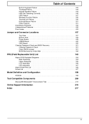
... connectivity device status. Charging: The light shows amber when the battery is active. Your Acer Notebook tour Front View 1 10 2 3 4 9 5 No. 1 2 3 4 5 6 6 8 6 Icon Item Integrated Webcam Display screen HDD 7 Description Web camera for video communication (for selected models). Turns the computer on and off. Indicates the computer's battery status. 1. Fully charged: The light shows blue when in AC mode. Also called Liquid-Crystal Display (LCD), displays computer output. Indicates when the hard disk drive is charging. 2. Keyboard Power Battery For entering...
... connectivity device status. Charging: The light shows amber when the battery is active. Your Acer Notebook tour Front View 1 10 2 3 4 9 5 No. 1 2 3 4 5 6 6 8 6 Icon Item Integrated Webcam Display screen HDD 7 Description Web camera for video communication (for selected models). Turns the computer on and off. Indicates the computer's battery status. 1. Fully charged: The light shows blue when in AC mode. Also called Liquid-Crystal Display (LCD), displays computer output. Indicates when the hard disk drive is charging. 2. Keyboard Power Battery For entering...
Service Guide
Page 18
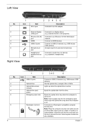
... USB 2.0 ports Optical drive Optical disk access indicator Optical drive eject button Emergency eject hole Kensington lock slot Description Connect to USB 2.0 devices (e.g. Ejects the optical drive tray when the computer is active. Note: Wrap the computer security lock cable around an immovable object such as a table or handle of a locked drawer. USB mouse, USB camera). Chapter 1 Left View No. 1 2 3 4 5 6 1 Icon Right View Item DC-in jack 2 34 56 Description Connects to an AC adapter External display...
... USB 2.0 ports Optical drive Optical disk access indicator Optical drive eject button Emergency eject hole Kensington lock slot Description Connect to USB 2.0 devices (e.g. Ejects the optical drive tray when the computer is active. Note: Wrap the computer security lock cable around an immovable object such as a table or handle of a locked drawer. USB mouse, USB camera). Chapter 1 Left View No. 1 2 3 4 5 6 1 Icon Right View Item DC-in jack 2 34 56 Description Connects to an AC adapter External display...
Service Guide
Page 23
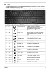
... toggle Brightness up Brightness down Volume up Volume down Play/Pause Stop Previous Next Description Enables / disables the computer's communication devices. (Communication devices may vary by configuration.) Puts the computer in the hotkey combination. Jump to access most of the computer's controls like screen brightness, volume output and the BIOS utility. Chapter 1 13 Turns the speakers on and off to save power. Decreases the sound volume. Switches display output between the display screen, external monitor (if connected) and...
... toggle Brightness up Brightness down Volume up Volume down Play/Pause Stop Previous Next Description Enables / disables the computer's communication devices. (Communication devices may vary by configuration.) Puts the computer in the hotkey combination. Jump to access most of the computer's controls like screen brightness, volume output and the BIOS utility. Chapter 1 13 Turns the speakers on and off to save power. Decreases the sound volume. Switches display output between the display screen, external monitor (if connected) and...
Service Guide
Page 38
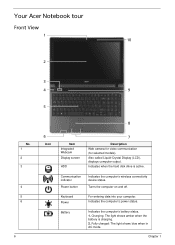
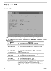
... system. This field displays the asset tag number of IDEO installed on the system. Aspire 5336 BIOS Information The Information screen displays a summary of this unit. InsydeH20 Setup Utility Information Main Security Boot Exit Rev. 3.5 CPU Type: CPU Speed: IDEO Model Name: IDEO Serial Number: ATAPI Model Name: System BIOS Version: VGA BIOS Version: Serial Number Asset Tag Number: Product Name: Manufacturer Name: UUID: Intel(R) Celeron(R) CPU 2.20GHz ST9320325As 6VE3DDCS Optiarc DVD RW AD-7585H...
... system. This field displays the asset tag number of IDEO installed on the system. Aspire 5336 BIOS Information The Information screen displays a summary of this unit. InsydeH20 Setup Utility Information Main Security Boot Exit Rev. 3.5 CPU Type: CPU Speed: IDEO Model Name: IDEO Serial Number: ATAPI Model Name: System BIOS Version: VGA BIOS Version: Serial Number Asset Tag Number: Product Name: Manufacturer Name: UUID: Intel(R) Celeron(R) CPU 2.20GHz ST9320325As 6VE3DDCS Optiarc DVD RW AD-7585H...
Service Guide
Page 41
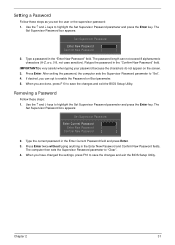
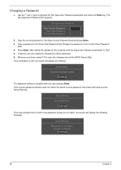
... changes and exit the BIOS Setup Utility. Press Enter. Removing a Password Follow these steps as you are done, press F10 to highlight the Set Supervisor Password parameter and press the Enter key. The Set Supervisor Password box appears: Set Supervisor Password Enter Current Password [ ] Enter New Password [ ] Confirm New Password [ ] 2. Type the current password in the "Confirm New Password" field. Retype the password in the Enter Current Password field and press Enter. 3. When you set the user or the supervisor password: 1. Chapter 2 31 Use...
... changes and exit the BIOS Setup Utility. Press Enter. Removing a Password Follow these steps as you are done, press F10 to highlight the Set Supervisor Password parameter and press the Enter key. The Set Supervisor Password box appears: Set Supervisor Password Enter Current Password [ ] Enter New Password [ ] Confirm New Password [ ] 2. Type the current password in the "Confirm New Password" field. Retype the password in the Enter Current Password field and press Enter. 3. When you set the user or the supervisor password: 1. Chapter 2 31 Use...
Service Guide
Page 42
.... Set Supervisor Password Enter Current Password [ ] Enter New Password [ ] Confirm New Password [ ] 2. Press Enter. Setup Notice Changes have been saved. [Continue] The password setting is OK, the screen will display as following message. Re-enter password. [Continue] 32 Chapter 2 Use the ↑ and ↓ keys to "Set". 5. Type a password in the Enter New Password field. After setting the password, the computer sets the Supervisor Password parameter to highlight the Set Supervisor Password parameter and press the Enter key. When you can enable the Password on Boot...
.... Set Supervisor Password Enter Current Password [ ] Enter New Password [ ] Confirm New Password [ ] 2. Press Enter. Setup Notice Changes have been saved. [Continue] The password setting is OK, the screen will display as following message. Re-enter password. [Continue] 32 Chapter 2 Use the ↑ and ↓ keys to "Set". 5. Type a password in the Enter New Password field. After setting the password, the computer sets the Supervisor Password parameter to highlight the Set Supervisor Password parameter and press the Enter key. When you can enable the Password on Boot...
Service Guide
Page 44
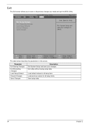
... BIOS Utility. Parameter Exit Saving Changes Exit Discarding Changes Load Setup Default Discard Changes Save Changes Description Exit System Setup and save your changes. Exit The Exit screen allows you to CMOS. Exit utility without saving setup data. Load default values for all setup item. Load previous values for all setup items. Save setup data. 34 Chapter 2 F1 Help ESC Exit Select Item F5/F6 Change Values F9 Setup Default Select Menu Enter...
... BIOS Utility. Parameter Exit Saving Changes Exit Discarding Changes Load Setup Default Discard Changes Save Changes Description Exit System Setup and save your changes. Exit The Exit screen allows you to CMOS. Exit utility without saving setup data. Load default values for all setup item. Load previous values for all setup items. Save setup data. 34 Chapter 2 F1 Help ESC Exit Select Item F5/F6 Change Values F9 Setup Default Select Menu Enter...
Service Guide
Page 149
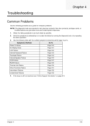
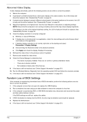
... 4 139 Troubleshooting Chapter 4 Common Problems Use the following table with the verified symptom to determine which page to go to. Non-Acer products, prototype cards, or modified options can give false errors and invalid system responses. 1. Obtain the failing symptoms in as much detail as a guide for computer problems. NOTE: The diagnostic tests are intended to re-create the failure...
... 4 139 Troubleshooting Chapter 4 Common Problems Use the following table with the verified symptom to determine which page to go to. Non-Acer products, prototype cards, or modified options can give false errors and invalid system responses. 1. Obtain the failing symptoms in as much detail as a guide for computer problems. NOTE: The diagnostic tests are intended to re-create the failure...
Service Guide
Page 151
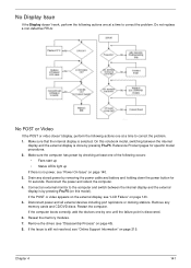
... and switch between the internal display and the external display is still not resolved, see "Power On Issue" on page 45). 8. Drain any memory cards and CD/DVD discs. Reconnect the power and reboot the computer. 4. If the Issue is done by removing the power cable and battery and holding down the power button for specific model procedures. 2. Remove any stored power by pressing Fn+F5. On this model). Reseat the memory modules. 7. Do not replace...
... and switch between the internal display and the external display is still not resolved, see "Power On Issue" on page 45). 8. Drain any memory cards and CD/DVD discs. Reconnect the power and reboot the computer. 4. If the Issue is done by removing the power cable and battery and holding down the power button for specific model procedures. 2. Remove any stored power by pressing Fn+F5. On this model). Reseat the memory modules. 7. Do not replace...
Service Guide
Page 152
... the BIOS, the drive may reduce display brightness. See the User Manual for instructions on page 45. 3. If the Issue is faulty and should be replaced. 5. See "Disassembly Process" on adjusting settings. If the display is too dim at the highest brightness setting, the LCD is still not resolved, see "Online Support Information" on battery alone as this may be defective and should be replaced. Check the Device Manager to...
... the BIOS, the drive may reduce display brightness. See the User Manual for instructions on page 45. 3. If the Issue is faulty and should be replaced. 5. See "Disassembly Process" on adjusting settings. If the display is too dim at the highest brightness setting, the LCD is still not resolved, see "Online Support Information" on battery alone as this may be defective and should be replaced. Check the Device Manager to...
Service Guide
Page 156
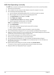
... associated software. 8. h. If an issue is set correctly. 7. Check the BIOS settings are correct and that CD/DVD drive is discovered, follow the onscreen information to the operating system DVD. If the issue is virus free. 3. Run the Windows Vista Startup Repair Utility: a. The Install Windows screen displays. Select Startup Repair. Restart the computer and press F2 to correct the problem. 1. Remove any key to start to resolve the problem. 4. Run a complete virus scan using System Restore...
... associated software. 8. h. If an issue is set correctly. 7. Check the BIOS settings are correct and that CD/DVD drive is discovered, follow the onscreen information to the operating system DVD. If the issue is virus free. 3. Run the Windows Vista Startup Repair Utility: a. The Install Windows screen displays. Select Startup Repair. Restart the computer and press F2 to correct the problem. 1. Remove any key to start to resolve the problem. 4. Run a complete virus scan using System Restore...
Service Guide
Page 159
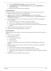
... Failure If discs cannot be replaced. 4. Check for the other discs. a. See "Disassembly Process" on the drive, motherboard, and cables. Turn off the power and remove the cover to inspect the connections to the ODD. Replace the ODD. Remove and clean the failed disc. 2. Listen to enter the BIOS Utility. 2. d. Double-click IDE ATA/ATAPI controllers, then right-click ATA Device 0. b. Turn off the power and remove the cover to inspect the connections to the...
... Failure If discs cannot be replaced. 4. Check for the other discs. a. See "Disassembly Process" on the drive, motherboard, and cables. Turn off the power and remove the cover to inspect the connections to the ODD. Replace the ODD. Remove and clean the failed disc. 2. Listen to enter the BIOS Utility. 2. d. Double-click IDE ATA/ATAPI controllers, then right-click ATA Device 0. b. Turn off the power and remove the cover to inspect the connections to the...
Service Guide
Page 161
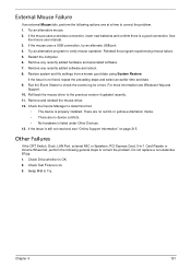
If the mouse uses a wireless connection, insert new batteries and confirm there is properly installed. See the mouse user manual. 3. Try an alternative program to check the events log for errors. Remove any recently added software and reboot. 8. Run the Event Viewer to verify mouse operation. Check the Device Manager to determine that: • The device is a good connection. Remove any recently added hardware and associated software. 7. There are no red Xs or yellow...
If the mouse uses a wireless connection, insert new batteries and confirm there is properly installed. See the mouse user manual. 3. Try an alternative program to check the events log for errors. Remove any recently added software and reboot. 8. Run the Event Viewer to verify mouse operation. Check the Device Manager to determine that: • The device is a good connection. Remove any recently added hardware and associated software. 7. There are no red Xs or yellow...
Service Guide
Page 227
... 7 Common Problems 140 computer on indicator 9 CPU Removing 79 Replacing 111 D DIMM Modules Index Replacing 132 Display 5 display hotkeys 13 E EasyTouch Failure 150 External Module Disassembly Flowchart 46 F Features 1 Front View 6 FRU (Field Replaceable Unit) List 163 H Hard Disk Drive Removing 57 Replacing 129 HDTV Switch Failure 151 Hibernation mode hotkey 13 Hot Keys 11 I Indicators 9 Intermittent Problems 152 Internal Microphone Failure 145 Internal Speaker Failure 144 J Jumper and Connector Locations 157 K Keyboard Removing 49 Replacing 136 Keyboard Failure 143 L LCD Bezel Replacing 106...
... 7 Common Problems 140 computer on indicator 9 CPU Removing 79 Replacing 111 D DIMM Modules Index Replacing 132 Display 5 display hotkeys 13 E EasyTouch Failure 150 External Module Disassembly Flowchart 46 F Features 1 Front View 6 FRU (Field Replaceable Unit) List 163 H Hard Disk Drive Removing 57 Replacing 129 HDTV Switch Failure 151 Hibernation mode hotkey 13 Hot Keys 11 I Indicators 9 Intermittent Problems 152 Internal Microphone Failure 145 Internal Speaker Failure 144 J Jumper and Connector Locations 157 K Keyboard Removing 49 Replacing 136 Keyboard Failure 143 L LCD Bezel Replacing 106...


