Quick Start Guide
Page 11
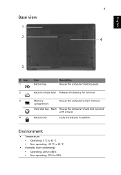
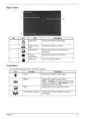
Main Houses the computer's hard disk (secured with screws). 4 Battery lock Locks the battery in position. Environment • Temperature: • Operating: 5 °C to 35 °C • Non-operating: -20 °C to 65 °C • Humidity (non-condensing): • Operating: 20% to 80% • Non-operating: 20% to 80% compartment Hard disk bay - English 9 Base view 1 2 4 3 # Icon 1 Item Battery bay Description Houses the computer's battery pack. 2 Battery release latch Releases the battery for removal. 3 Memory Houses the computer's main memory.
Main Houses the computer's hard disk (secured with screws). 4 Battery lock Locks the battery in position. Environment • Temperature: • Operating: 5 °C to 35 °C • Non-operating: -20 °C to 65 °C • Humidity (non-condensing): • Operating: 20% to 80% • Non-operating: 20% to 80% compartment Hard disk bay - English 9 Base view 1 2 4 3 # Icon 1 Item Battery bay Description Houses the computer's battery pack. 2 Battery release latch Releases the battery for removal. 3 Memory Houses the computer's main memory.
Service Guide
Page 6
... fit local market requirements and enhance product competitiveness, your regional web or channel. In such cases, please contact your regional Acer office to -date information available on card, modem, or extra memory capability). You MUST use the list provided by your regional offices or the responsible personnel/channel to provide you with...
... fit local market requirements and enhance product competitiveness, your regional web or channel. In such cases, please contact your regional Acer office to -date information available on card, modem, or extra memory capability). You MUST use the list provided by your regional offices or the responsible personnel/channel to provide you with...
Service Guide
Page 11
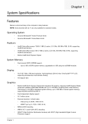
...; Dual-channel DDR3 SDRAM support: • Up to 2 GB of DDR3 system memory, upgradable to 4 GB using two soDIMM modules Display • • 15.6" HD 1366 x 768 pixel resolution, high-brightness (200-nit) Acer CineCrystal™ TFT LCD, supporting simultaneous multi-window viewing 16:9 aspect ratio Graphics • Mobile Intel® GL40...
...; Dual-channel DDR3 SDRAM support: • Up to 2 GB of DDR3 system memory, upgradable to 4 GB using two soDIMM modules Display • • 15.6" HD 1366 x 768 pixel resolution, high-brightness (200-nit) Acer CineCrystal™ TFT LCD, supporting simultaneous multi-window viewing 16:9 aspect ratio Graphics • Mobile Intel® GL40...
Service Guide
Page 19
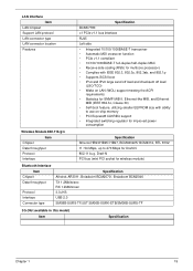
... disk drive is charging. 2. Communication indicator Indicates the computer's wireless connectivity device status. Battery release latch Hard disk bay Memory compartment Battery lock Releases the battery for removal. Houses the computer's main memory. Charging: The light shows amber when the battery is active. Chapter 1 9 Locks the battery in AC mode. Indicators The...
... disk drive is charging. 2. Communication indicator Indicates the computer's wireless connectivity device status. Battery release latch Hard disk bay Memory compartment Battery lock Releases the battery for removal. Houses the computer's main memory. Charging: The light shows amber when the battery is active. Chapter 1 9 Locks the battery in AC mode. Indicators The...

Service Guide
Page 25
... & Model Name WD WD1600BEVT22A23T0 HITACHI HTS545016B9A300 SEAGATE ST9160314AS TOSHIBA MK1665GSX Capacity (GB) 160GB Bytes per socket Supports maximum memory size Supports DIMM type Supports DIMM Speed Support DIMM voltage Supports DIMM package Specification Built in (Intel® GL40 ...form other combinations. In the above table, the configuration of slot 1 and slot 2 could be reversed. System Memory Item Memory controller Memory size DIMM socket number Supports memory size per sector 512Bytes Data heads 1 2 2 1 Drive Format Disks 1 Spindle speed (RPM) 5400 Performance ...
... & Model Name WD WD1600BEVT22A23T0 HITACHI HTS545016B9A300 SEAGATE ST9160314AS TOSHIBA MK1665GSX Capacity (GB) 160GB Bytes per socket Supports maximum memory size Supports DIMM type Supports DIMM Speed Support DIMM voltage Supports DIMM package Specification Built in (Intel® GL40 ...form other combinations. In the above table, the configuration of slot 1 and slot 2 could be reversed. System Memory Item Memory controller Memory size DIMM socket number Supports memory size per sector 512Bytes Data heads 1 2 2 1 Drive Format Disks 1 Spindle speed (RPM) 5400 Performance ...

Service Guide
Page 28
...Specification With CD Diskette With DVD Diskette Transfer rate (KB/sec) Sustained: Max 3.6Mbytes/sec Sustained: Max 10.08Mbytes/sec Buffer Memory 2MB Interface SATA Applicable disc format Applicable disc format CD: CD-DA, CD-ROM, CD-ROM XA, Photo CD (multi-session... Requirement Input Voltage 5 V +/- 5% (Operating) BD Drive Interface Item Vendor & model name Performance Specification Transfer rate (KB/sec) Buffer Memory Interface Applicable disc format Loading mechanism Power Requirement Input Voltage Specification HLDS BD COMBO DRIVE TRAY DL 4X CT10 LF, PANASONIC BD COMBO 12.7mm...
...Specification With CD Diskette With DVD Diskette Transfer rate (KB/sec) Sustained: Max 3.6Mbytes/sec Sustained: Max 10.08Mbytes/sec Buffer Memory 2MB Interface SATA Applicable disc format Applicable disc format CD: CD-DA, CD-ROM, CD-ROM XA, Photo CD (multi-session... Requirement Input Voltage 5 V +/- 5% (Operating) BD Drive Interface Item Vendor & model name Performance Specification Transfer rate (KB/sec) Buffer Memory Interface Applicable disc format Loading mechanism Power Requirement Input Voltage Specification HLDS BD COMBO DRIVE TRAY DL 4X CT10 LF, PANASONIC BD COMBO 12.7mm...
Service Guide
Page 29
..., Ethernet-like MIB, and Ethernet MIB (IEEE 802.3z, Clause 30) • Self-boot feature, utilizing smaller EEPROM size with ability to use on-chip memory • PCI Express® CLKREQ support • Integrated switching regulator for improved power consumption Wireless Module 802.11b/g/n Item Chipset Data throughput Protocol Interface Specification...
..., Ethernet-like MIB, and Ethernet MIB (IEEE 802.3z, Clause 30) • Self-boot feature, utilizing smaller EEPROM size with ability to use on-chip memory • PCI Express® CLKREQ support • Integrated switching regulator for improved power consumption Wireless Module 802.11b/g/n Item Chipset Data throughput Protocol Interface Specification...
Service Guide
Page 30
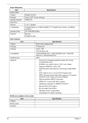
... 10 fully programmable cores • 400-MHz core render clock at 1.05-V core voltage • Supports iHDMI/DVI, LVDS, CRT • Intel® Dynamic Video Memory Technology (Intel® DVMT 5.0) • Video Capture via x1 concurrent PCI Express port • PAVP (Protected Audio-Video Path) support for Protected Intel® HD... DirectX10 support • Blu-ray support @ 40 Mb/s • Hardware motion compensation • Intermediate Z in classic rendering VRAM (not available in this model) Item Chipset Memory size Interface Specification 20 Chapter 1
... 10 fully programmable cores • 400-MHz core render clock at 1.05-V core voltage • Supports iHDMI/DVI, LVDS, CRT • Intel® Dynamic Video Memory Technology (Intel® DVMT 5.0) • Video Capture via x1 concurrent PCI Express port • PAVP (Protected Audio-Video Path) support for Protected Intel® HD... DirectX10 support • Blu-ray support @ 40 Mb/s • Hardware motion compensation • Intermediate Z in classic rendering VRAM (not available in this model) Item Chipset Memory size Interface Specification 20 Chapter 1
Service Guide
Page 39
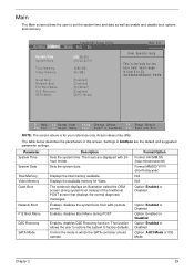
... the system time and date as well as enable and disable boot options and recovery. Parameter System Time System Date Total Memory Video Memory Quiet Boot Network Boot F12 Boot Menu D2D Recovery SATA Mode Description Sets the system time. The notebook displays an illustration ... defaults. Sets the system date. Enables, disables D2D Recovery function. Information Main InsydeH20 Setup Utility Security Boot Exit System Time System Date Total Memory: Video Memory: Quiet Boot Network Boot F12 Boot Menu D2D Recovery SATA Mode [08:56:55] [02/25/2010] 4095 MB [64 MB] [...
... the system time and date as well as enable and disable boot options and recovery. Parameter System Time System Date Total Memory Video Memory Quiet Boot Network Boot F12 Boot Menu D2D Recovery SATA Mode Description Sets the system time. The notebook displays an illustration ... defaults. Sets the system date. Enables, disables D2D Recovery function. Information Main InsydeH20 Setup Utility Security Boot Exit System Time System Date Total Memory: Video Memory: Quiet Boot Network Boot F12 Boot Menu D2D Recovery SATA Mode [08:56:55] [02/25/2010] 4095 MB [64 MB] [...
Service Guide
Page 45
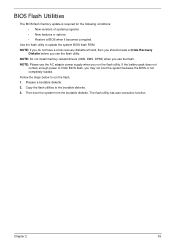
If the battery pack does not contain enough power to run the flash utility. NOTE: Do not install memory-related drivers (XMS, EMS, DPMI) when you run the flash. 1. Prepare a bootable diskette. 2. NOTE: Please use the AC adaptor power supply when you use the ... when it becomes corrupted. Use the flash utility to the bootable diskette. 3. The flash utility has auto-execution function. BIOS Flash Utilities The BIOS flash memory update is not completely loaded. Then boot the system from the bootable diskette. Follow the steps below to finish BIOS flash, you use the flash...
If the battery pack does not contain enough power to run the flash utility. NOTE: Do not install memory-related drivers (XMS, EMS, DPMI) when you run the flash. 1. Prepare a bootable diskette. 2. NOTE: Please use the AC adaptor power supply when you use the ... when it becomes corrupted. Use the flash utility to the bootable diskette. 3. The flash utility has auto-execution function. BIOS Flash Utilities The BIOS flash memory update is not completely loaded. Then boot the system from the bootable diskette. Follow the steps below to finish BIOS flash, you use the flash...
Service Guide
Page 52
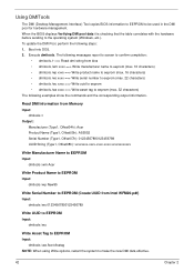
...the commands and the corresponding output information. Boot into DOS. 2. Execute dmitools. Read DMI Information from Memory Input: dmitools /r Output: Manufacturer (Type1, Offset04h): Acer Product Name (Type1, Offset05h): AS5552 Serial Number (Type1, Offset07h): 01234567890123456789 UUID String (Type1, Offset08h...): xxxxxxxx-xxxx-xxxx-xxxx-xxxxxxxxxxxx Write Manufacturer Name to EEPROM Input: dmitools /wm Acer Write Product Name to EEPROM Input: dmitools /wp New95 Write Serial Number to EEPROM (Create UUID from bios • dmitools...
...the commands and the corresponding output information. Boot into DOS. 2. Execute dmitools. Read DMI Information from Memory Input: dmitools /r Output: Manufacturer (Type1, Offset04h): Acer Product Name (Type1, Offset05h): AS5552 Serial Number (Type1, Offset07h): 01234567890123456789 UUID String (Type1, Offset08h...): xxxxxxxx-xxxx-xxxx-xxxx-xxxxxxxxxxxx Write Manufacturer Name to EEPROM Input: dmitools /wm Acer Write Product Name to EEPROM Input: dmitools /wp New95 Write Serial Number to EEPROM (Create UUID from bios • dmitools...
Service Guide
Page 151
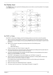
... one by one at a time to the computer and switch between the internal display and the external display is by pressing Fn+F5. Reseat the memory modules. 7. If the POST or video appears on the external display, see "Disassembly Process" on page 143. 5. Drain any... memory cards and CD/DVD discs. Remove any stored power by checking at least one at a time to correct the problem. No Display Issue If the ...
... one by one at a time to the computer and switch between the internal display and the external display is by pressing Fn+F5. Reseat the memory modules. 7. If the POST or video appears on the external display, see "Disassembly Process" on page 143. 5. Drain any... memory cards and CD/DVD discs. Remove any stored power by checking at least one at a time to correct the problem. No Display Issue If the ...
Service Guide
Page 152
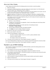
..., perform the following actions one at the highest brightness setting, the LCD is more than one at a time to correct the problem. 1. Run the Windows Memory Diagnostic from the BIOS, the drive may reduce display brightness. Run a complete virus scan using up-to-date software to its highest level.
..., perform the following actions one at the highest brightness setting, the LCD is more than one at a time to correct the problem. 1. Run the Windows Memory Diagnostic from the BIOS, the drive may reduce display brightness. Run a complete virus scan using up-to-date software to its highest level.

Service Guide
Page 156
... computer. The Install Windows screen displays. Click Next. Select the appropriate operating system, and click Next. g. i. If an issue is set correctly. 7. Run the Windows Memory Diagnostic Tool. Check the BIOS settings are set as the first boot device on the Boot menu. 6. Remove any key to start to ensure the...
... computer. The Install Windows screen displays. Click Next. Select the appropriate operating system, and click Next. g. i. If an issue is set correctly. 7. Run the Windows Memory Diagnostic Tool. Check the BIOS settings are set as the first boot device on the Boot menu. 6. Remove any key to start to ensure the...

Service Guide
Page 163
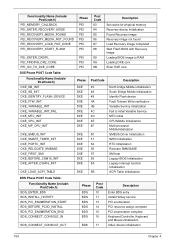
Memory Initial for Normal boot. Post Codes These tables describe the POST codes and descriptions during the POST. Post Code Range SEC PEI DXE BDS SMM ... Initial HyperTransport Initialization PCIE MMIO BAR Initialization North Bridge Early Initialization South Bridge Early Initialization PCIE Training TPM Initialization SMBUS Early Initialization Clock Generator Initialization Memory Initial for Crisis Recovery Simple Memory test Start to use...
Memory Initial for Normal boot. Post Codes These tables describe the POST codes and descriptions during the POST. Post Code Range SEC PEI DXE BDS SMM ... Initial HyperTransport Initialization PCIE MMIO BAR Initialization North Bridge Early Initialization South Bridge Early Initialization PCIE Training TPM Initialization SMBUS Early Initialization Clock Generator Initialization Memory Initial for Crisis Recovery Simple Memory test Start to use...
Service Guide
Page 164
... PEI PEI PEI PEI PEI PEI PEI PEI PEI Post Code 83 84 85 86 87 88 89 8A 8B Description Set cache for physical memory Recovery device Initialization Found Recovery image Recovery image not found Load Recovery Image completed Start Flash BIOS with Recovery image Loading BIOS image to RAM...
... PEI PEI PEI PEI PEI PEI PEI PEI PEI Post Code 83 84 85 86 87 88 89 8A 8B Description Set cache for physical memory Recovery device Initialization Found Recovery image Recovery image not found Load Recovery Image completed Start Flash BIOS with Recovery image Loading BIOS image to RAM...
Service Guide
Page 168
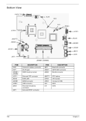
Bottom View PJP2 JCPU1 PJP1 U23 U11 JFAN1 JCRT1 JBATT1 JMINI1 JHDD1 JBT1 ITEM PJP2 PJP1 JDIMM1 / JDIMM2 JCRT1 JRJ45 JHDMI1 JUSB1 JMIC1 JHP1 JDIMM1/JDIMM2 DESCRIPTION Connect to battery connector DC-IN jack DDR3 memory socket ITEM JBT1 JHDD1 JMINI1 DESCRIPTION Bluetooth connector SATA HDD connector WLAN connector External CRT connector RJ45 LAN HDMI connector USB connector External microphone connector External SPDIF connector JBATT1 JCPU1 JFAN1 U23 U11 RTC battery CPU socket Connect to FAN MCH ICH9 JRJ45 JHDMI1 JUSB1 JMIC1 JHP1 158 Chapter 3
Bottom View PJP2 JCPU1 PJP1 U23 U11 JFAN1 JCRT1 JBATT1 JMINI1 JHDD1 JBT1 ITEM PJP2 PJP1 JDIMM1 / JDIMM2 JCRT1 JRJ45 JHDMI1 JUSB1 JMIC1 JHP1 JDIMM1/JDIMM2 DESCRIPTION Connect to battery connector DC-IN jack DDR3 memory socket ITEM JBT1 JHDD1 JMINI1 DESCRIPTION Bluetooth connector SATA HDD connector WLAN connector External CRT connector RJ45 LAN HDMI connector USB connector External microphone connector External SPDIF connector JBATT1 JCPU1 JFAN1 U23 U11 RTC battery CPU socket Connect to FAN MCH ICH9 JRJ45 JHDMI1 JUSB1 JMIC1 JHP1 158 Chapter 3
Service Guide
Page 195
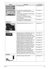
Category MAINBOARD Description LED BRACKET R&L Acer Part No. 33.R4F02.004 LED LCD AUO 15.6"W WXGA GLARE B156XW02 V2 LF 200NIT 8MS 500:1 (POWER SAVING) LED LCD CMO 15.6"W WXGA GLARE ....1560D.010 LK.15608.011 LK.1560A.004 MAINBOARD AS5336 INTEL GL40 V1.0 LF MB.R4G02.001 MEMORY HEATSINK MEMORY ELPIDA SO-DIMM DDRIII 1333 1GB EBJ10UE8BDS0-DJ-F LF 128*8 0.065UM MEMORY KINGSTON SO-DIMM DDRIII 1333 1GB ACR128X64D3S1333C9 LF 128*8 0.065UM MEMORY SAMSUNG SO-DIMM DDRIII 1333 1GB M471B2873FHS-CH9 LF 128*8 46NM...
Category MAINBOARD Description LED BRACKET R&L Acer Part No. 33.R4F02.004 LED LCD AUO 15.6"W WXGA GLARE B156XW02 V2 LF 200NIT 8MS 500:1 (POWER SAVING) LED LCD CMO 15.6"W WXGA GLARE ....1560D.010 LK.15608.011 LK.1560A.004 MAINBOARD AS5336 INTEL GL40 V1.0 LF MB.R4G02.001 MEMORY HEATSINK MEMORY ELPIDA SO-DIMM DDRIII 1333 1GB EBJ10UE8BDS0-DJ-F LF 128*8 0.065UM MEMORY KINGSTON SO-DIMM DDRIII 1333 1GB ACR128X64D3S1333C9 LF 128*8 0.065UM MEMORY SAMSUNG SO-DIMM DDRIII 1333 1GB M471B2873FHS-CH9 LF 128*8 46NM...
Service Guide
Page 223
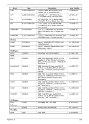
Brand CMO CPT LPL LPL Type NLED15.6WXGAG NLED15.6WXGAG N15.6WXGAG NLED15.6WXGAG SAMSUNG N15.6WXGAG SAMSUNG Memory NONE NONE NB Chipset INTEL ODD HLDS NLED15.6WXGAG SO1GBIII10 SO2GBIII10 GL40(A1) NSM8XS PANASONIC NSM8XS PLDS NSM8XS SONY NSM8XS SONY NSM8XS TOSHIBA NSM8XS SB ... LCD SAMSUNG 15.6"W WXGA Glare LTN156AT02-A04 LF 220nit 8ms 500:1 Acer Part No LK.1560D.010 LK.1560A.004 LK.15608.013 LK.15608.011 LK.15606.001 LK.15606.009 Memory NONE REG-ECC DDRIII 1066 1GB phantom p/n LF Memory NONE SO-DIMM DDRIII 1066 2GB dummy 1066 LF KN.1GB00...
Brand CMO CPT LPL LPL Type NLED15.6WXGAG NLED15.6WXGAG N15.6WXGAG NLED15.6WXGAG SAMSUNG N15.6WXGAG SAMSUNG Memory NONE NONE NB Chipset INTEL ODD HLDS NLED15.6WXGAG SO1GBIII10 SO2GBIII10 GL40(A1) NSM8XS PANASONIC NSM8XS PLDS NSM8XS SONY NSM8XS SONY NSM8XS TOSHIBA NSM8XS SB ... LCD SAMSUNG 15.6"W WXGA Glare LTN156AT02-A04 LF 220nit 8ms 500:1 Acer Part No LK.1560D.010 LK.1560A.004 LK.15608.013 LK.15608.011 LK.15606.001 LK.15606.009 Memory NONE REG-ECC DDRIII 1066 1GB phantom p/n LF Memory NONE SO-DIMM DDRIII 1066 2GB dummy 1066 LF KN.1GB00...
Service Guide
Page 228
... Removing 89 Replacing 98 Left View 8 LVDS Cable Replacing 100 M Main Unit Disassembly Flowchart 60 Mainboard Removing 74 Replacing 114 media access on indicator 9 Memory Replacing 132 Memory Check 140 Model Definition 188 N No Display Issue 141 O ODD Connector Board Removing 73 Replacing 117 ODD Failure 147 Online Support Information 215 Optical...
... Removing 89 Replacing 98 Left View 8 LVDS Cable Replacing 100 M Main Unit Disassembly Flowchart 60 Mainboard Removing 74 Replacing 114 media access on indicator 9 Memory Replacing 132 Memory Check 140 Model Definition 188 N No Display Issue 141 O ODD Connector Board Removing 73 Replacing 117 ODD Failure 147 Online Support Information 215 Optical...


