Service Guide
Page 8
...Removing the Camera Module 86 Removing the Inverter Board 87 Removing the LCD/LED Panel 89 Removing the LCD Brackets 90 Removing the LVDS cable 91 Removing the Microphone Cable 92 Removing the Antennas 94 LCD Module Reassembly Procedure 96 Replacing the Antennas 96 Replacing the Microphone ...Cable 98 Replacing the LVDS Cable 100 Replacing the LCD Brackets 101 Replacing the LCD/LED Panel 102 Removing the Inverter Board 103 Replacing the Camera Module 105 Replacing the LCD Bezel 106 Main Module Reassembly Procedure 107 Replacing the DC-IN Assembly 107...
...Removing the Camera Module 86 Removing the Inverter Board 87 Removing the LCD/LED Panel 89 Removing the LCD Brackets 90 Removing the LVDS cable 91 Removing the Microphone Cable 92 Removing the Antennas 94 LCD Module Reassembly Procedure 96 Replacing the Antennas 96 Replacing the Microphone ...Cable 98 Replacing the LVDS Cable 100 Replacing the LCD Brackets 101 Replacing the LCD/LED Panel 102 Removing the Inverter Board 103 Replacing the Camera Module 105 Replacing the LCD Bezel 106 Main Module Reassembly Procedure 107 Replacing the DC-IN Assembly 107...
Service Guide
Page 55
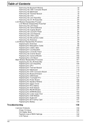
... disassembly The flowcharts provided in that order. The disassembly process is faulty, such as the camera, antenna or LCD panel, the whole module must first remove the keyboard, then disassemble the inside assembly frame in the succeeding disassembly sections illustrate the entire disassembly sequence. Main ....004 M2.5*5 13 86.R4F02.001 M1.98*3 4 86.R4F02.008 M2.5*6 2 86.R4F02.003 M3*3 4 86.R4F02.005 Chapter 3 45 Disassembly Process IMPORTANT: The LCD Module cannot be replaced.
... disassembly The flowcharts provided in that order. The disassembly process is faulty, such as the camera, antenna or LCD panel, the whole module must first remove the keyboard, then disassemble the inside assembly frame in the succeeding disassembly sections illustrate the entire disassembly sequence. Main ....004 M2.5*5 13 86.R4F02.001 M1.98*3 4 86.R4F02.008 M2.5*6 2 86.R4F02.003 M3*3 4 86.R4F02.005 Chapter 3 45 Disassembly Process IMPORTANT: The LCD Module cannot be replaced.
Service Guide
Page 85
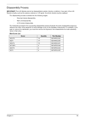
Step Mainboard Size M2.5*5 Quantity 1 Screw Type 6. Chapter 3 75 5. To prevent damage, lay the LCD panel flat and cover the panel as shown. Remove the one (1) securing screw from the mainboard.
Step Mainboard Size M2.5*5 Quantity 1 Screw Type 6. Chapter 3 75 5. To prevent damage, lay the LCD panel flat and cover the panel as shown. Remove the one (1) securing screw from the mainboard.
Service Guide
Page 86
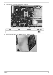
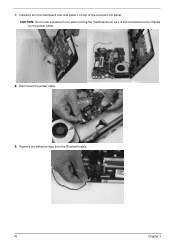
Disconnect the power cable. 9. Remove the adhesive tape from the Bluetooth cable. 76 Chapter 3 CAUTION: Do not use excessive force when turning the mainboard over and place it is still connected to the chassis by the power cable. 8. Carefully turn the mainboard over as it on top of the covered LCD panel. 7.
Disconnect the power cable. 9. Remove the adhesive tape from the Bluetooth cable. 76 Chapter 3 CAUTION: Do not use excessive force when turning the mainboard over and place it is still connected to the chassis by the power cable. 8. Carefully turn the mainboard over as it on top of the covered LCD panel. 7.
Service Guide
Page 94
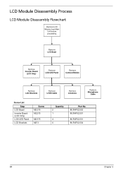
LCD Module Disassembly Process LCD Module Disassembly Flowchart Remove LCD Module from Main Unit before proceeding Remove LCD Bezel Remove Inverter Board (LCD Only) Remove LCD/LED Panel Remove Camera Module Remove LCD Brackets Remove LVDS Cable Remove Antennas Remove Microphone Cable Screw List Step LCD Bezel Inverter Board (LCD Only) LCD/LED Panel LCD Brackets Screw M2.5*6 M2.5*5 M2.5*5 M2*3 Quantity 2 1 4 6 Part No. 86.R4F02.003 86.R4F02.001 86.R4F02.001 86.R4F02.004 84 Chapter 3
LCD Module Disassembly Process LCD Module Disassembly Flowchart Remove LCD Module from Main Unit before proceeding Remove LCD Bezel Remove Inverter Board (LCD Only) Remove LCD/LED Panel Remove Camera Module Remove LCD Brackets Remove LVDS Cable Remove Antennas Remove Microphone Cable Screw List Step LCD Bezel Inverter Board (LCD Only) LCD/LED Panel LCD Brackets Screw M2.5*6 M2.5*5 M2.5*5 M2*3 Quantity 2 1 4 6 Part No. 86.R4F02.003 86.R4F02.001 86.R4F02.001 86.R4F02.004 84 Chapter 3
Service Guide
Page 95
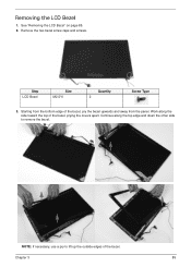
Continue along the side toward the top of the bezel, prying the covers apart. See "Removing the LCD Bezel" on page 85. 2. Work along the top edge and down the other side to lift up the outside edges of the bezel, pry the bezel upwards and away from the panel. NOTE: If necessary, use a pry to remove the bezel. Step LCD Bezel Size M2.5*6 Quantity 2 Screw Type 3. Chapter 3 85 Removing the LCD Bezel 1. Remove the two bezel screw caps and screws. Starting from the bottom edge of the bezel.
Continue along the side toward the top of the bezel, prying the covers apart. See "Removing the LCD Bezel" on page 85. 2. Work along the top edge and down the other side to lift up the outside edges of the bezel, pry the bezel upwards and away from the panel. NOTE: If necessary, use a pry to remove the bezel. Step LCD Bezel Size M2.5*6 Quantity 2 Screw Type 3. Chapter 3 85 Removing the LCD Bezel 1. Remove the two bezel screw caps and screws. Starting from the bottom edge of the bezel.
Service Guide
Page 97
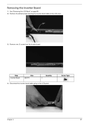
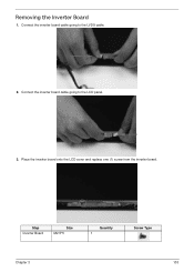
Step Inverter Board Size M2.5*5 Quantity 1 4. See "Removing the LCD Bezel" on page 85. 2. Screw Type Chapter 3 87 Removing the Inverter Board 1. Remove one (1) screw from the inverter board. Remove the adhesive tape securing the inverter board cable to the LCD panel. Disconnect the inverter board cable going to the LCD cover. 3.
Step Inverter Board Size M2.5*5 Quantity 1 4. See "Removing the LCD Bezel" on page 85. 2. Screw Type Chapter 3 87 Removing the Inverter Board 1. Remove one (1) screw from the inverter board. Remove the adhesive tape securing the inverter board cable to the LCD panel. Disconnect the inverter board cable going to the LCD cover. 3.
Service Guide
Page 99
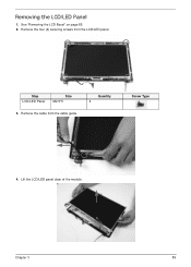
Remove the cable from the LCD/LED panel. Lift the LCD/LED panel clear of the module. Chapter 3 89 Step LCD/LED Panel Size M2.5*5 3. Quantity 4 Screw Type 4. Remove the four (4) securing screws from the cable guide. Removing the LCD/LED Panel 1. See "Removing the LCD Bezel" on page 85. 2.
Remove the cable from the LCD/LED panel. Lift the LCD/LED panel clear of the module. Chapter 3 89 Step LCD/LED Panel Size M2.5*5 3. Quantity 4 Screw Type 4. Remove the four (4) securing screws from the cable guide. Removing the LCD/LED Panel 1. See "Removing the LCD Bezel" on page 85. 2.
Service Guide
Page 100
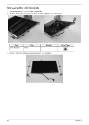
Screw Type 90 Chapter 3 Step LCD Brackets Size M2*3 Quantity 6 3. Remove the six (6) securing screws (three on page 89. 2. Remove the LCD brackets by pulling away from the LCD brackets. See "Removing the LCD/LED Panel" on each side) from the LCD panel. Removing the LCD Brackets 1.
Screw Type 90 Chapter 3 Step LCD Brackets Size M2*3 Quantity 6 3. Remove the six (6) securing screws (three on page 89. 2. Remove the LCD brackets by pulling away from the LCD brackets. See "Removing the LCD/LED Panel" on each side) from the LCD panel. Removing the LCD Brackets 1.

Service Guide
Page 101
Remove the LVDS cable from the panel. Disconnect the LVDS cable and remove it from the back of the panel. See "Removing the LCD/LED Panel" on page 89. 2. Peel back the mylar securing the LVDS cable. Removing the LVDS cable 1. LCD LED Chapter 3 91 LCD LED 3. LCD LED 4.
Remove the LVDS cable from the panel. Disconnect the LVDS cable and remove it from the back of the panel. See "Removing the LCD/LED Panel" on page 89. 2. Peel back the mylar securing the LVDS cable. Removing the LVDS cable 1. LCD LED Chapter 3 91 LCD LED 3. LCD LED 4.
Service Guide
Page 102
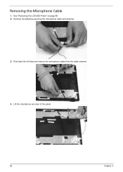
See "Removing the LCD/LED Panel" on page 89. 2. Remove the adhesive securing the microphone cable and antenna. 3. Peel back the foil tabs and remove the microphone cable from the cable channel. 4. Lift the microphone set clear of the panel. 92 Chapter 3 Removing the Microphone Cable 1.
See "Removing the LCD/LED Panel" on page 89. 2. Remove the adhesive securing the microphone cable and antenna. 3. Peel back the foil tabs and remove the microphone cable from the cable channel. 4. Lift the microphone set clear of the panel. 92 Chapter 3 Removing the Microphone Cable 1.
Service Guide
Page 104
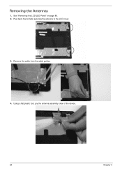
Using a flat plastic tool, pry the antenna assembly clear of the device. 94 Chapter 3 Remove the cable from the cable guides. 4. Peel back the foil tabs securing the antenna to the LCD cover. 3. Removing the Antennas 1. See "Removing the LCD/LED Panel" on page 89. 2.
Using a flat plastic tool, pry the antenna assembly clear of the device. 94 Chapter 3 Remove the cable from the cable guides. 4. Peel back the foil tabs securing the antenna to the LCD cover. 3. Removing the Antennas 1. See "Removing the LCD/LED Panel" on page 89. 2.
Service Guide
Page 108
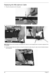
Fold over the foil tabs and continue running the microphone cable along the cable channel. Place the microphone set in the LCD module. 3. Run the cable along the cable channel indicated between the callouts to avoid trapping when the panel is replaced in the panel. 2. Replacing the Microphone Cable 1. IMPORTANT: Ensure that the cable runs between the red callouts. 98 Chapter 3
Fold over the foil tabs and continue running the microphone cable along the cable channel. Place the microphone set in the LCD module. 3. Run the cable along the cable channel indicated between the callouts to avoid trapping when the panel is replaced in the panel. 2. Replacing the Microphone Cable 1. IMPORTANT: Ensure that the cable runs between the red callouts. 98 Chapter 3
Service Guide
Page 110
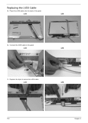
LCD LED 100 Chapter 3 Connect the LVDS cable to secure the LVDS cable. LCD LED 6. Replace the mylar to the panel. LCD LED 7. Replacing the LVDS Cable 5. Place the LVDS cable onto the back of the panel.
LCD LED 100 Chapter 3 Connect the LVDS cable to secure the LVDS cable. LCD LED 6. Replace the mylar to the panel. LCD LED 7. Replacing the LVDS Cable 5. Place the LVDS cable onto the back of the panel.
Service Guide
Page 111
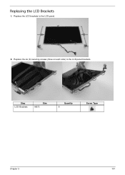
Replacing the LCD Brackets 1. Replace the LCD brackets to the LCD panel brackets. Replace the six (6) securing screws (three on each side) to the LCD panel. 2. Step LCD Brackets Size M2*3 Quantity 6 Screw Type Chapter 3 101
Replacing the LCD Brackets 1. Replace the LCD brackets to the LCD panel brackets. Replace the six (6) securing screws (three on each side) to the LCD panel. 2. Step LCD Brackets Size M2*3 Quantity 6 Screw Type Chapter 3 101
Service Guide
Page 112
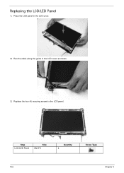
Step LCD/LED Panel Size M2.5*5 Quantity 4 Screw Type 102 Chapter 3 Replace the four (4) securing screws to the LCD panel. Replacing the LCD/LED Panel 1. Run the cable along the guide in the LCD cover. 2. Place the LCD panel in the LCD cover as shown. 3.
Step LCD/LED Panel Size M2.5*5 Quantity 4 Screw Type 102 Chapter 3 Replace the four (4) securing screws to the LCD panel. Replacing the LCD/LED Panel 1. Run the cable along the guide in the LCD cover. 2. Place the LCD panel in the LCD cover as shown. 3.
Service Guide
Page 113
Step Inverter Board Size M2.5*5 Quantity 1 Screw Type Chapter 3 103 Connect the inverter board cable going to the LVDS cable. 2. Place the inverter board onto the LCD cover and replace one (1) screw from the inverter board. Connect the inverter board cable going to the LCD panel. 3. Removing the Inverter Board 1.
Step Inverter Board Size M2.5*5 Quantity 1 Screw Type Chapter 3 103 Connect the inverter board cable going to the LVDS cable. 2. Place the inverter board onto the LCD cover and replace one (1) screw from the inverter board. Connect the inverter board cable going to the LCD panel. 3. Removing the Inverter Board 1.
Service Guide
Page 228
... Removing 90, 91 Replacing 98 LCD Cable Replacing 98 LCD Failure 143 LCD Module Disassembly Flowchart 84 LCD Module Reassembly Procedure 96 LCD Panel Removing 89 Replacing 98 Left View 8 LVDS Cable Replacing 100 M Main Unit Disassembly Flowchart 60 Mainboard Removing 74 Replacing 114 media access... Board Removing 73 Replacing 117 ODD Failure 147 Online Support Information 215 Optical Disk Drive Replacing 133, 134 Optical Drive Module Removing 51 218 P Panel 6 PC Card 9 Power On Failure 140 R Replacing 122 Right Speaker Module Removing 65 Replacing 122 Right View 8 S SD Dummy Card Removing...
... Removing 90, 91 Replacing 98 LCD Cable Replacing 98 LCD Failure 143 LCD Module Disassembly Flowchart 84 LCD Module Reassembly Procedure 96 LCD Panel Removing 89 Replacing 98 Left View 8 LVDS Cable Replacing 100 M Main Unit Disassembly Flowchart 60 Mainboard Removing 74 Replacing 114 media access... Board Removing 73 Replacing 117 ODD Failure 147 Online Support Information 215 Optical Disk Drive Replacing 133, 134 Optical Drive Module Removing 51 218 P Panel 6 PC Card 9 Power On Failure 140 R Replacing 122 Right Speaker Module Removing 65 Replacing 122 Right View 8 S SD Dummy Card Removing...


