Service Guide
Page 7
Table of Contents System Specifications 1 Features 1 System Block Diagram 5 Your Acer Notebook tour 6 Front View 6 Closed Front View 7 Closed Rear View 7 Left View 8 Right View 8 Base View 9 Indicators 9 Touchpad Basics 10 ...Utility 27 Aspire 5336 BIOS 28 Information 28 Main 29 Security 30 Boot 33 Exit 34 BIOS Flash Utilities 35 DOS Flash Utility 36 WinFlash Utility 38 Remove HDD/BIOS Password Utilities 39 Machine Disassembly and Replacement 43 Disassembly Requirements 43 Pre-disassembly Instructions 44 Disassembly Process 45 External Module Disassembly Process 46...
Table of Contents System Specifications 1 Features 1 System Block Diagram 5 Your Acer Notebook tour 6 Front View 6 Closed Front View 7 Closed Rear View 7 Left View 8 Right View 8 Base View 9 Indicators 9 Touchpad Basics 10 ...Utility 27 Aspire 5336 BIOS 28 Information 28 Main 29 Security 30 Boot 33 Exit 34 BIOS Flash Utilities 35 DOS Flash Utility 36 WinFlash Utility 38 Remove HDD/BIOS Password Utilities 39 Machine Disassembly and Replacement 43 Disassembly Requirements 43 Pre-disassembly Instructions 44 Disassembly Process 45 External Module Disassembly Process 46...
Service Guide
Page 8
... 74 Removing the Thermal Module 78 Removing the CPU 79 Removing the LCD Assembly 80 Removing the DC-IN Assembly 83 LCD Module Disassembly Process 84 LCD Module Disassembly Flowchart 84 Removing the LCD Bezel 85 Removing the Camera Module 86 Removing the Inverter Board 87 Removing the LCD/LED Panel 89...
... 74 Removing the Thermal Module 78 Removing the CPU 79 Removing the LCD Assembly 80 Removing the DC-IN Assembly 83 LCD Module Disassembly Process 84 LCD Module Disassembly Flowchart 84 Removing the LCD Bezel 85 Removing the Camera Module 86 Removing the Inverter Board 87 Removing the LCD/LED Panel 89...
Service Guide
Page 53
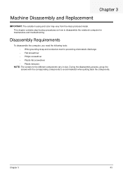
... Replacement IMPORTANT: The outside housing and color may vary from the mass produced model. Disassembly Requirements To disassemble the computer, you need the following tools: • Wrist grounding strap and conductive mat for preventing electrostatic discharge • Flat screwdriver • Philips screwdriver • ...
... Replacement IMPORTANT: The outside housing and color may vary from the mass produced model. Disassembly Requirements To disassemble the computer, you need the following tools: • Wrist grounding strap and conductive mat for preventing electrostatic discharge • Flat screwdriver • Philips screwdriver • ...
Service Guide
Page 54
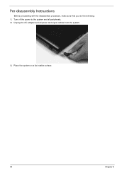
Pre-disassembly Instructions Before proceeding with the disassembly procedure, make sure that you do the following: 1. Place the system on a flat, stable surface. 44 Chapter 3 Turn off the power to the system and all power and signal cables from the system. 3. Unplug the AC adapter and all peripherals. 2.
Pre-disassembly Instructions Before proceeding with the disassembly procedure, make sure that you do the following: 1. Place the system on a flat, stable surface. 44 Chapter 3 Turn off the power to the system and all power and signal cables from the system. 3. Unplug the AC adapter and all peripherals. 2.
Service Guide
Page 55
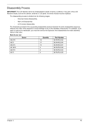
..., such as the camera, antenna or LCD panel, the whole module must first remove the keyboard, then disassemble the inside assembly frame in the succeeding disassembly sections illustrate the entire disassembly sequence. Main Screw List Screw Quantity Part Number M2.5*8 19 86.R4F02.002 M2*3 17 86.R4F02.004... M1.98*3 4 86.R4F02.008 M2.5*6 2 86.R4F02.003 M3*3 4 86.R4F02.005 Chapter 3 45 For example, if you must be disassembled outside of the hardware components. Observe the order of the sequence to avoid damage to remove the mainboard, you want to any part of the...
..., such as the camera, antenna or LCD panel, the whole module must first remove the keyboard, then disassemble the inside assembly frame in the succeeding disassembly sections illustrate the entire disassembly sequence. Main Screw List Screw Quantity Part Number M2.5*8 19 86.R4F02.002 M2*3 17 86.R4F02.004... M1.98*3 4 86.R4F02.008 M2.5*6 2 86.R4F02.003 M3*3 4 86.R4F02.005 Chapter 3 45 For example, if you must be disassembled outside of the hardware components. Observe the order of the sequence to avoid damage to remove the mainboard, you want to any part of the...

Service Guide
Page 56
Turn off system and peripherals power Disconnect power and signal cables from the mass produced model. External Module Disassembly Process IMPORTANT: The outside housing and color may vary from system Remove Battery Remove SD Dummy Card Remove Lower Logic Door Remove ODD ... 86.R4F02.002 86.R4F02.004 86.R4F02.002 86.R4F02.004 86.R4F02.005 Chapter 3 External Modules Disassembly Flowchart The flowchart below gives you a graphic representation of the external module disassembly sequence and instructs you on the components that need to remove the keyboard, you want to be removed during...
Turn off system and peripherals power Disconnect power and signal cables from the mass produced model. External Module Disassembly Process IMPORTANT: The outside housing and color may vary from system Remove Battery Remove SD Dummy Card Remove Lower Logic Door Remove ODD ... 86.R4F02.002 86.R4F02.004 86.R4F02.002 86.R4F02.004 86.R4F02.005 Chapter 3 External Modules Disassembly Flowchart The flowchart below gives you a graphic representation of the external module disassembly sequence and instructs you on the components that need to remove the keyboard, you want to be removed during...
Service Guide
Page 70
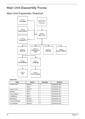
Main Unit Disassembly Process Main Unit Disassembly Flowchart Remove Power Board Remove External Modules before proceeding Remove Speaker Module Remove Touchpad FFC Remove Upper Cover Remove Mainboard Remove ODD Connector Board Remove ...
Main Unit Disassembly Process Main Unit Disassembly Flowchart Remove Power Board Remove External Modules before proceeding Remove Speaker Module Remove Touchpad FFC Remove Upper Cover Remove Mainboard Remove ODD Connector Board Remove ...

Service Guide
Page 71
See "External Module Disassembly Process" on the lower cover and four (4) screws from the battery bay. Step Lower Cover Size M2.5*8 (red callout) M2*3 (green callout) Quantity 10 4 Screw Type Chapter 3 61 Turn the computer over. Remove the ten (10) screws on page 46. 2. Removing the Upper Cover 1.
See "External Module Disassembly Process" on the lower cover and four (4) screws from the battery bay. Step Lower Cover Size M2.5*8 (red callout) M2*3 (green callout) Quantity 10 4 Screw Type Chapter 3 61 Turn the computer over. Remove the ten (10) screws on page 46. 2. Removing the Upper Cover 1.
Service Guide
Page 94
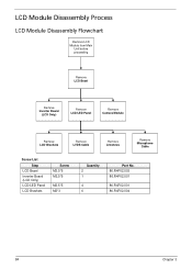
LCD Module Disassembly Process LCD Module Disassembly Flowchart Remove LCD Module from Main Unit before proceeding Remove LCD Bezel Remove Inverter Board (LCD Only) Remove LCD/LED Panel Remove Camera Module Remove LCD Brackets Remove LVDS Cable Remove Antennas Remove Microphone Cable Screw List Step LCD Bezel Inverter Board (LCD Only) LCD/LED Panel LCD Brackets Screw M2.5*6 M2.5*5 M2.5*5 M2*3 Quantity 2 1 4 6 Part No. 86.R4F02.003 86.R4F02.001 86.R4F02.001 86.R4F02.004 84 Chapter 3
LCD Module Disassembly Process LCD Module Disassembly Flowchart Remove LCD Module from Main Unit before proceeding Remove LCD Bezel Remove Inverter Board (LCD Only) Remove LCD/LED Panel Remove Camera Module Remove LCD Brackets Remove LVDS Cable Remove Antennas Remove Microphone Cable Screw List Step LCD Bezel Inverter Board (LCD Only) LCD/LED Panel LCD Brackets Screw M2.5*6 M2.5*5 M2.5*5 M2*3 Quantity 2 1 4 6 Part No. 86.R4F02.003 86.R4F02.001 86.R4F02.001 86.R4F02.004 84 Chapter 3
Service Guide
Page 151
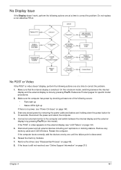
... power and reboot the computer. 4. Remove the drives (see "LCD Failure" on page 143. 5. If the POST or video appears on the external display, see "Disassembly Process" on page 215. Restart the computer. Drain any memory cards and CD/DVD discs. If the computer boots correctly, add the devices one by...
... power and reboot the computer. 4. Remove the drives (see "LCD Failure" on page 143. 5. If the POST or video appears on the external display, see "Disassembly Process" on page 215. Restart the computer. Drain any memory cards and CD/DVD discs. If the computer boots correctly, add the devices one by...
Service Guide
Page 152
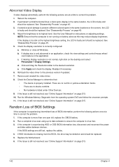
...replaced. Run the Windows Memory Diagnostic from the BIOS, the drive may reduce display brightness. Replace the Motherboard. 6. See "Disassembly Process" on adjusting settings. Check the Device Manager to determine that the computer is experiencing intermittent loss of BIOS Settings If ... no red Xs or yellow exclamation marks. • There are still lost, replace the cables. 4. Readjust if necessary. 6. See "Disassembly Process" on page 45. 5. If the computer is experiencing HDD or ODD BIOS information loss, disconnect and reconnect the power and data cables...
...replaced. Run the Windows Memory Diagnostic from the BIOS, the drive may reduce display brightness. Replace the Motherboard. 6. See "Disassembly Process" on adjusting settings. Check the Device Manager to determine that the computer is experiencing intermittent loss of BIOS Settings If ... no red Xs or yellow exclamation marks. • There are still lost, replace the cables. 4. Readjust if necessary. 6. See "Disassembly Process" on page 45. 5. If the computer is experiencing HDD or ODD BIOS information loss, disconnect and reconnect the power and data cables...
Service Guide
Page 156
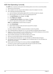
... Finish. If an issue is discovered, follow the onscreen information to locate and resolve issues with the computer. If the issue is set correctly. 7. See "Disassembly Process" on the Boot menu. 6. HDD Not Operating Correctly If the HDD does not operate correctly, perform the following actions one at a time to ensure...
... Finish. If an issue is discovered, follow the onscreen information to locate and resolve issues with the computer. If the issue is set correctly. 7. See "Disassembly Process" on the Boot menu. 6. HDD Not Operating Correctly If the HDD does not operate correctly, perform the following actions one at a time to ensure...
Service Guide
Page 159
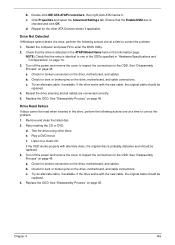
...page 45. Reseat the drive ensuring and all cables are connected correctly. 5. Remove and clean the failed disc. 2. Listen to the ODD. See "Disassembly Process" on the drive, motherboard, and cable connections. Chapter 4 149 Ensure that the entry is checked and click OK. Restart the computer and ...: Check that the Enable DMA box is identical to one of the ODDs specified in the ATAPI Model Name field on page 14. 3. See "Disassembly Process" on the drive, motherboard, and cables. Check for the other discs. Play a DVD movie f. Try an alternate cable, if available. If...
...page 45. Reseat the drive ensuring and all cables are connected correctly. 5. Remove and clean the failed disc. 2. Listen to the ODD. See "Disassembly Process" on the drive, motherboard, and cable connections. Chapter 4 149 Ensure that the entry is checked and click OK. Restart the computer and ...: Check that the Enable DMA box is identical to one of the ODDs specified in the ATAPI Model Name field on page 14. 3. See "Disassembly Process" on the drive, motherboard, and cables. Check for the other discs. Play a DVD movie f. Try an alternate cable, if available. If...
Service Guide
Page 227
... 7 Common Problems 140 computer on indicator 9 CPU Removing 79 Replacing 111 D DIMM Modules Index Replacing 132 Display 5 display hotkeys 13 E EasyTouch Failure 150 External Module Disassembly Flowchart 46 F Features 1 Front View 6 FRU (Field Replaceable Unit) List 163 H Hard Disk Drive Removing 57 Replacing 129 HDTV Switch Failure 151 Hibernation mode hotkey...
... 7 Common Problems 140 computer on indicator 9 CPU Removing 79 Replacing 111 D DIMM Modules Index Replacing 132 Display 5 display hotkeys 13 E EasyTouch Failure 150 External Module Disassembly Flowchart 46 F Features 1 Front View 6 FRU (Field Replaceable Unit) List 163 H Hard Disk Drive Removing 57 Replacing 129 HDTV Switch Failure 151 Hibernation mode hotkey...
Service Guide
Page 228
... 84 LCD Module Reassembly Procedure 96 LCD Panel Removing 89 Replacing 98 Left View 8 LVDS Cable Replacing 100 M Main Unit Disassembly Flowchart 60 Mainboard Removing 74 Replacing 114 media access on indicator 9 Memory Replacing 132 Memory Check 140 Model Definition 188 N No Display Issue 141 O ODD ...
... 84 LCD Module Reassembly Procedure 96 LCD Panel Removing 89 Replacing 98 Left View 8 LVDS Cable Replacing 100 M Main Unit Disassembly Flowchart 60 Mainboard Removing 74 Replacing 114 media access on indicator 9 Memory Replacing 132 Memory Check 140 Model Definition 188 N No Display Issue 141 O ODD ...


