Service Guide
Page 7
... Contents System Specifications 1 Features 1 System Block Diagram 5 Your Acer Notebook tour 6 Front View 6 Closed Front View 7 Closed Rear View 7 Left View 8 Right View 8 Base View 9 Indicators 9 Touchpad Basics 10 Using the Keyboard 11 Lock Keys and embedded numeric keypad 11 Windows Keys 12 ...Navigating the BIOS Utility 27 Aspire 5336 BIOS 28 Information 28 Main 29 Security 30 Boot 33 Exit 34 BIOS Flash Utilities 35 DOS Flash Utility 36 WinFlash Utility 38 Remove HDD/BIOS Password Utilities 39 Machine Disassembly and Replacement 43 Disassembly Requirements 43 ...
... Contents System Specifications 1 Features 1 System Block Diagram 5 Your Acer Notebook tour 6 Front View 6 Closed Front View 7 Closed Rear View 7 Left View 8 Right View 8 Base View 9 Indicators 9 Touchpad Basics 10 Using the Keyboard 11 Lock Keys and embedded numeric keypad 11 Windows Keys 12 ...Navigating the BIOS Utility 27 Aspire 5336 BIOS 28 Information 28 Main 29 Security 30 Boot 33 Exit 34 BIOS Flash Utilities 35 DOS Flash Utility 36 WinFlash Utility 38 Remove HDD/BIOS Password Utilities 39 Machine Disassembly and Replacement 43 Disassembly Requirements 43 ...
Service Guide
Page 8
... 119 Replacing the Touchpad FFC 121 Replacing the Power Board 122 Replacing the Speaker Module 123 Replacing the Upper Cover 124 Replacing the RTC Battery 128 Replacing the HDD Module 129 Replacing the WLAN Module 131 Replacing the DIMM Modules 132 Replacing the Lower Logic Door 133 Replacing the ODD Module 134 Replacing the Keyboard 136 Replacing the SD Dummy Card 137 Replacing the...
... 119 Replacing the Touchpad FFC 121 Replacing the Power Board 122 Replacing the Speaker Module 123 Replacing the Upper Cover 124 Replacing the RTC Battery 128 Replacing the HDD Module 129 Replacing the WLAN Module 131 Replacing the DIMM Modules 132 Replacing the Lower Logic Door 133 Replacing the ODD Module 134 Replacing the Keyboard 136 Replacing the SD Dummy Card 137 Replacing the...
Service Guide
Page 9
Table of Contents Built-In Keyboard Failure 143 Touchpad Failure 144 Internal Speaker Failure 144 HDD Not Operating Correctly 146 ODD Failure 147 Wireless Function Failure 150 Thermal Unit Failure 150 ... Clearing Password Check 161 Clear CMOS Jumper 161 BIOS Recovery by Crisis Disk 162 FRU (Field Replaceable Unit) List 163 Aspire 5336 Exploded Diagrams 164 Main Assembly 164 Upper Assembly 165 LCD Assembly 166 LED Assembly 167 Aspire 5336 FRU List 168 Screw List 187 Model Definition and Configuration 188 AS5336 188 Test Compatible Components...
Table of Contents Built-In Keyboard Failure 143 Touchpad Failure 144 Internal Speaker Failure 144 HDD Not Operating Correctly 146 ODD Failure 147 Wireless Function Failure 150 Thermal Unit Failure 150 ... Clearing Password Check 161 Clear CMOS Jumper 161 BIOS Recovery by Crisis Disk 162 FRU (Field Replaceable Unit) List 163 Aspire 5336 Exploded Diagrams 164 Main Assembly 164 Upper Assembly 165 LCD Assembly 166 LED Assembly 167 Aspire 5336 FRU List 168 Screw List 187 Model Definition and Configuration 188 AS5336 188 Test Compatible Components...
Service Guide
Page 55
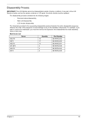
If any of the hardware components. Disassembly Process IMPORTANT: The LCD Module cannot be replaced. For example, if you want to any part of factory conditions. Main Screw List Screw Quantity Part Number M2.5*8 19 86.R4F02.002 M2*3 17 ... flowcharts provided in that order. The disassembly process is faulty, such as the camera, antenna or LCD panel, the whole module must first remove the keyboard, then disassemble the inside assembly frame in the succeeding disassembly sections illustrate the entire disassembly sequence.
If any of the hardware components. Disassembly Process IMPORTANT: The LCD Module cannot be replaced. For example, if you want to any part of factory conditions. Main Screw List Screw Quantity Part Number M2.5*8 19 86.R4F02.002 M2*3 17 ... flowcharts provided in that order. The disassembly process is faulty, such as the camera, antenna or LCD panel, the whole module must first remove the keyboard, then disassemble the inside assembly frame in the succeeding disassembly sections illustrate the entire disassembly sequence.
Service Guide
Page 146
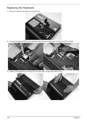
Connect the keyboard FPC to the mainboard and close the locking latch to lock. 136 Chapter 3 Press down on the palm rest. 2. Replacing the Keyboard 1. Replace the keyboard by first lining up the bottom edge. Place the keyboard face down firmly to secure the FPC in place. 3.
Connect the keyboard FPC to the mainboard and close the locking latch to lock. 136 Chapter 3 Press down on the palm rest. 2. Replacing the Keyboard 1. Replace the keyboard by first lining up the bottom edge. Place the keyboard face down firmly to secure the FPC in place. 3.
Service Guide
Page 153
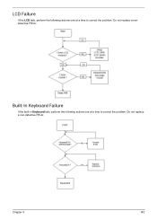
Do not replace a non-defective FRUs: Chapter 4 143 Do not replace a nondefective FRUs: Built-In Keyboard Failure If the built-in Keyboard fails, perform the following actions one at a time to correct the problem. LCD Failure If the LCD fails, perform the following actions one at a time to correct the problem.
Do not replace a non-defective FRUs: Chapter 4 143 Do not replace a nondefective FRUs: Built-In Keyboard Failure If the built-in Keyboard fails, perform the following actions one at a time to correct the problem. LCD Failure If the LCD fails, perform the following actions one at a time to correct the problem.
Service Guide
Page 227
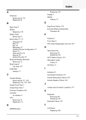
...hotkeys 13 C Camera Module Removing 86, 87, 103 Replacing 102, 105, 108 Closed Front View 7 Closed Rear View 7 Common Problems 140 computer on indicator 9 CPU Removing 79 Replacing 111 D DIMM Modules Index Replacing 132 Display 5 display hotkeys 13 E EasyTouch Failure 150... Replaceable Unit) List 163 H Hard Disk Drive Removing 57 Replacing 129 HDTV Switch Failure 151 Hibernation mode hotkey 13 Hot Keys 11 I Indicators 9 Intermittent Problems 152 Internal Microphone Failure 145 Internal Speaker Failure 144 J Jumper and Connector Locations 157 K Keyboard Removing 49 Replacing 136 Keyboard Failure...
...hotkeys 13 C Camera Module Removing 86, 87, 103 Replacing 102, 105, 108 Closed Front View 7 Closed Rear View 7 Common Problems 140 computer on indicator 9 CPU Removing 79 Replacing 111 D DIMM Modules Index Replacing 132 Display 5 display hotkeys 13 E EasyTouch Failure 150... Replaceable Unit) List 163 H Hard Disk Drive Removing 57 Replacing 129 HDTV Switch Failure 151 Hibernation mode hotkey 13 Hot Keys 11 I Indicators 9 Intermittent Problems 152 Internal Microphone Failure 145 Internal Speaker Failure 144 J Jumper and Connector Locations 157 K Keyboard Removing 49 Replacing 136 Keyboard Failure...


