Quick Start Guide
Page 7
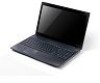
... Power button / indicator Keyboard Power indicator Indicates the computer's wireless connectivity device status. Touch-sensitive pointing device which functions like the left and right) Touchpad Speaker Microphone 2-in AC mode. For entering data into your computer. Fully charged: The light shows blue when in -1 card reader Indicates the computer's battery status...
... Power button / indicator Keyboard Power indicator Indicates the computer's wireless connectivity device status. Touch-sensitive pointing device which functions like the left and right) Touchpad Speaker Microphone 2-in AC mode. For entering data into your computer. Fully charged: The light shows blue when in -1 card reader Indicates the computer's battery status...
Quick Start Guide
Page 8
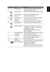
... the other key in Sleep mode. + + + + Display toggle Screen blank Touchpad toggle Switches display output between the display screen, external monitor (if connected) and both. Speaker toggle Turns the speakers on and off to save power. English 6 Hotkeys The computer employs hotkeys or key combinations to return.
... the other key in Sleep mode. + + + + Display toggle Screen blank Touchpad toggle Switches display output between the display screen, external monitor (if connected) and both. Speaker toggle Turns the speakers on and off to save power. English 6 Hotkeys The computer employs hotkeys or key combinations to return.
Quick Start Guide
Page 9
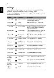
based network. 4 HDMI port Supports high-definition digital video connections. 5 USB 2.0 port Connect to audio line-out devices line-out jack (e.g., speakers, headphones). Headphone/speaker/ Connects to USB 2.0 devices (e.g., USB mouse, USB camera). 6 Microphone jack Accepts inputs from external microphones. English 7 Rear view # Item 1 Battery bay Left view 1 Description Houses ...
based network. 4 HDMI port Supports high-definition digital video connections. 5 USB 2.0 port Connect to audio line-out devices line-out jack (e.g., speakers, headphones). Headphone/speaker/ Connects to USB 2.0 devices (e.g., USB mouse, USB camera). 6 Microphone jack Accepts inputs from external microphones. English 7 Rear view # Item 1 Battery bay Left view 1 Description Houses ...
Service Guide
Page 7
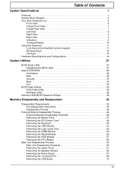
Table of Contents System Specifications 1 Features 1 System Block Diagram 5 Your Acer Notebook tour 6 Front View 6 Closed Front View 7 Closed Rear View 7 Left View 8 Right ...13 Hardware Specifications and Configurations 14 System Utilities 27 BIOS Setup Utility 27 Navigating the BIOS Utility 27 Aspire 5336 BIOS 28 Information 28 Main 29 Security 30 Boot 33 Exit 34 BIOS Flash Utilities 35 DOS Flash...Unit Disassembly Flowchart 60 Removing the Upper Cover 61 Removing the Speaker Module 65 Removing the Power Board 67 Removing the Touchpad FFC 69 Removing the USB Board 70 ...
Table of Contents System Specifications 1 Features 1 System Block Diagram 5 Your Acer Notebook tour 6 Front View 6 Closed Front View 7 Closed Rear View 7 Left View 8 Right ...13 Hardware Specifications and Configurations 14 System Utilities 27 BIOS Setup Utility 27 Navigating the BIOS Utility 27 Aspire 5336 BIOS 28 Information 28 Main 29 Security 30 Boot 33 Exit 34 BIOS Flash Utilities 35 DOS Flash...Unit Disassembly Flowchart 60 Removing the Upper Cover 61 Removing the Speaker Module 65 Removing the Power Board 67 Removing the Touchpad FFC 69 Removing the USB Board 70 ...
Service Guide
Page 8
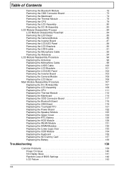
... Connector Board 117 Replacing the Bluetooth Board 118 Replacing the USB Board 119 Replacing the Touchpad FFC 121 Replacing the Power Board 122 Replacing the Speaker Module 123 Replacing the Upper Cover 124 Replacing the RTC Battery 128 Replacing the HDD Module 129 Replacing the WLAN Module 131 Replacing the DIMM...
... Connector Board 117 Replacing the Bluetooth Board 118 Replacing the USB Board 119 Replacing the Touchpad FFC 121 Replacing the Power Board 122 Replacing the Speaker Module 123 Replacing the Upper Cover 124 Replacing the RTC Battery 128 Replacing the HDD Module 129 Replacing the WLAN Module 131 Replacing the DIMM...
Service Guide
Page 9
Table of Contents Built-In Keyboard Failure 143 Touchpad Failure 144 Internal Speaker Failure 144 HDD Not Operating Correctly 146 ODD Failure 147 Wireless Function Failure 150 Thermal Unit Failure 150 External Mouse Failure 151 Other Failures ...161 Clear CMOS Jumper 161 BIOS Recovery by Crisis Disk 162 FRU (Field Replaceable Unit) List 163 Aspire 5336 Exploded Diagrams 164 Main Assembly 164 Upper Assembly 165 LCD Assembly 166 LED Assembly 167 Aspire 5336 FRU List 168 Screw List 187 Model Definition and Configuration 188 AS5336 188 Test Compatible Components 209 ...
Table of Contents Built-In Keyboard Failure 143 Touchpad Failure 144 Internal Speaker Failure 144 HDD Not Operating Correctly 146 ODD Failure 147 Wireless Function Failure 150 Thermal Unit Failure 150 External Mouse Failure 151 Other Failures ...161 Clear CMOS Jumper 161 BIOS Recovery by Crisis Disk 162 FRU (Field Replaceable Unit) List 163 Aspire 5336 Exploded Diagrams 164 Main Assembly 164 Upper Assembly 165 LCD Assembly 166 LED Assembly 167 Aspire 5336 FRU List 168 Screw List 187 Model Definition and Configuration 188 AS5336 188 Test Compatible Components 209 ...
Service Guide
Page 12
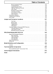
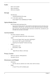
Audio • • • Built-in mono speaker Built-in microphone MS-Sound compatible Storage • • Hard disk drive: • 160/250/320/500/640 GB or larger 2-in-1 card reader, supporting: &#...-R DL, 4X DVD+R DL, 6X DVD-RW, 8X DVD+RW, 5X DVD-RAM Communication • Acer Video Conference, featuring: • Acer Crystal Eye webcam with 1280 x 1024 resolution • WLAN: • Acer InviLink™ Nplify™ 802.11b/g/n Wi-Fi CERTIFIED™ • Acer InviLink™ 802.11b/g Wi-Fi CERTIFIED™ • Supporting...
Audio • • • Built-in mono speaker Built-in microphone MS-Sound compatible Storage • • Hard disk drive: • 160/250/320/500/640 GB or larger 2-in-1 card reader, supporting: &#...-R DL, 4X DVD+R DL, 6X DVD-RW, 8X DVD+RW, 5X DVD-RAM Communication • Acer Video Conference, featuring: • Acer Crystal Eye webcam with 1280 x 1024 resolution • WLAN: • Acer InviLink™ Nplify™ 802.11b/g/n Wi-Fi CERTIFIED™ • Acer InviLink™ 802.11b/g Wi-Fi CERTIFIED™ • Supporting...
Service Guide
Page 13
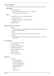
...;, MMC) • Three USB 2.0 ports • HDMI™ port with HDCP support • External display (VGA) port • Headphone/speaker/line-out jack • Microphone-in jack • Ethernet (RJ-45) port • DC-in jack for AC adapter Software • Productivity •...; Acer Backup Manager • Acer ePower Management • Acer eRecovery Management • Adobe® Flash® Player 10.1 • Adobe® Reader® 9.1 • eSobi™ •...
...;, MMC) • Three USB 2.0 ports • HDMI™ port with HDCP support • External display (VGA) port • Headphone/speaker/line-out jack • Microphone-in jack • Ethernet (RJ-45) port • DC-in jack for AC adapter Software • Productivity •...; Acer Backup Manager • Acer ePower Management • Acer eRecovery Management • Adobe® Flash® Player 10.1 • Adobe® Reader® 9.1 • eSobi™ •...

Service Guide
Page 17
No. 7 8 9 10 Icon Item Click buttons (left and right) Touchpad Speakers Microphone Description The left and right mouse buttons. Left and right speakers deliver stereo audio output. NOTE: The front panel indicators are visible even when the computer cover is closed. No. 1 Icon Item Battery bay 1 Description Houses ...
No. 7 8 9 10 Icon Item Click buttons (left and right) Touchpad Speakers Microphone Description The left and right mouse buttons. Left and right speakers deliver stereo audio output. NOTE: The front panel indicators are visible even when the computer cover is closed. No. 1 Icon Item Battery bay 1 Description Houses ...
Service Guide
Page 18
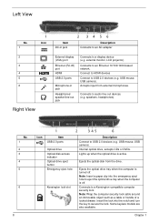
... 34 56 Description Connects to an AC adapter External display (VGA) port Ethernet (RJ-45) port HDMI USB 2.0 ports Microphone-in jack Headphones/ speaker/line-out jack Connects to USB 2.0 devices (e.g. Note: Insert a paper clip into the notch and turn the key to eject the optical drive tray...CDs or DVDs. Lights up when the optical drive is off . Connects to USB 2.0 devices (e.g. Ejects the optical disk from external microphones. speakers, headphones). USB mouse, USB camera). external monitor, LCD projector). Ejects the optical drive tray when the computer is turned off .
... 34 56 Description Connects to an AC adapter External display (VGA) port Ethernet (RJ-45) port HDMI USB 2.0 ports Microphone-in jack Headphones/ speaker/line-out jack Connects to USB 2.0 devices (e.g. Note: Insert a paper clip into the notch and turn the key to eject the optical drive tray...CDs or DVDs. Lights up when the optical drive is off . Connects to USB 2.0 devices (e.g. Ejects the optical disk from external microphones. speakers, headphones). USB mouse, USB camera). external monitor, LCD projector). Ejects the optical drive tray when the computer is turned off .
Service Guide
Page 23
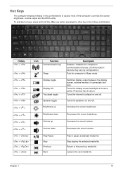
... power. Switches display output between the display screen, external monitor (if connected) and both. Turns the speakers on and off . Chapter 1 13 Hotkey + Icon Function Communication key + + + + + + < > + < > + < > + < > + + + + Sleep Display toggle Display Off Touchpad toggle Speaker toggle Brightness up Brightness down Volume up Volume down Play/Pause Stop Previous Next Description Enables / disables...
... power. Switches display output between the display screen, external monitor (if connected) and both. Turns the speakers on and off . Chapter 1 13 Hotkey + Icon Function Communication key + + + + + + < > + < > + < > + < > + + + + Sleep Display toggle Display Off Touchpad toggle Speaker toggle Brightness up Brightness down Volume up Volume down Play/Pause Stop Previous Next Description Enables / disables...
Service Guide
Page 30
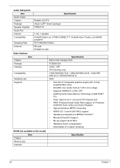
... Audio Port Internal Compatibility Sampling Rate External Specification Realtek ALC272 48-pin LQFP 'Green' package TPA6017A 1 mic, 1 speaker Dolby® Digital Live, DTS® CONNECT™, Dolby® Home Theater, and SRS® programs 44.1k/48k/96k/192kHz Mic jack Headphone jack ...
... Audio Port Internal Compatibility Sampling Rate External Specification Realtek ALC272 48-pin LQFP 'Green' package TPA6017A 1 mic, 1 speaker Dolby® Digital Live, DTS® CONNECT™, Dolby® Home Theater, and SRS® programs 44.1k/48k/96k/192kHz Mic jack Headphone jack ...
Service Guide
Page 70
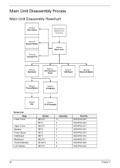
Main Unit Disassembly Process Main Unit Disassembly Flowchart Remove Power Board Remove External Modules before proceeding Remove Speaker Module Remove Touchpad FFC Remove Upper Cover Remove Mainboard Remove ODD Connector Board Remove USB Board Remove Bluetooth Module Remove... Thermal Module Remove LCD Module Remove CPU Remove DC-IN Assembly Screw List Step Lower Cover Upper Cover Speaker Power Board USB Board Mainboard Thermal Module LCD Module Screw M2.5*8 M2*3 M2.5*5 M2*3 M2*3 M2*3 M2.5*5 M1.98*3 M2.5*8 Quantity 11 4 7 2 1 1 1 ...
Main Unit Disassembly Process Main Unit Disassembly Flowchart Remove Power Board Remove External Modules before proceeding Remove Speaker Module Remove Touchpad FFC Remove Upper Cover Remove Mainboard Remove ODD Connector Board Remove USB Board Remove Bluetooth Module Remove... Thermal Module Remove LCD Module Remove CPU Remove DC-IN Assembly Screw List Step Lower Cover Upper Cover Speaker Power Board USB Board Mainboard Thermal Module LCD Module Screw M2.5*8 M2*3 M2.5*5 M2*3 M2*3 M2*3 M2.5*5 M1.98*3 M2.5*8 Quantity 11 4 7 2 1 1 1 ...
Service Guide
Page 73
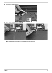
5. Disconnect the speaker cable (B). 6. Chapter 3 63 Unlock and disconnect the touchpad FFC (C). NOTE: Avoid pulling on cables directly to prevent damage to the connectors.
5. Disconnect the speaker cable (B). 6. Chapter 3 63 Unlock and disconnect the touchpad FFC (C). NOTE: Avoid pulling on cables directly to prevent damage to the connectors.
Service Guide
Page 75
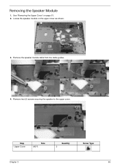
See "Removing the Upper Cover" on the upper cover as shown. 3. Remove the speaker module cable from the cable guides. 4. Locate the speaker module on page 61. 2. Step Upper Cover Size M2*3 Quantity 2 Screw Type Chapter 3 65 Remove two (2) screws securing the speaker to the upper cover. Removing the Speaker Module 1.
See "Removing the Upper Cover" on the upper cover as shown. 3. Remove the speaker module cable from the cable guides. 4. Locate the speaker module on page 61. 2. Step Upper Cover Size M2*3 Quantity 2 Screw Type Chapter 3 65 Remove two (2) screws securing the speaker to the upper cover. Removing the Speaker Module 1.
Service Guide
Page 76
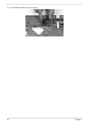
Lift the speaker module clear of the device. 66 Chapter 3 5.
Lift the speaker module clear of the device. 66 Chapter 3 5.
Service Guide
Page 133
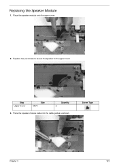
Replacing the Speaker Module 1. Replace two (2) screws to secure the speaker to the upper cover. Screw Type Chapter 3 123 Place the speaker module onto the upper cover. 2. Place the speaker module cable into the cable guides as shown. Step Upper Cover Size M2*3 Quantity 2 3.
Replacing the Speaker Module 1. Replace two (2) screws to secure the speaker to the upper cover. Screw Type Chapter 3 123 Place the speaker module onto the upper cover. 2. Place the speaker module cable into the cable guides as shown. Step Upper Cover Size M2*3 Quantity 2 3.
Service Guide
Page 136
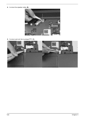
4. Connect and lock the touchpad FFC (C). 126 Chapter 3 Connect the speaker cable (B). 5.
4. Connect and lock the touchpad FFC (C). 126 Chapter 3 Connect the speaker cable (B). 5.
Service Guide
Page 149
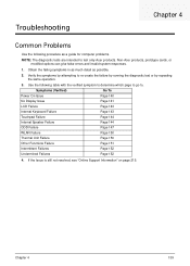
...Issue Page 140 No Display Issue Page 141 LCD Failure Page 143 Internal Keyboard Failure Page 143 Touchpad Failure Page 144 Internal Speaker Failure Page 144 ODD Failure Page 147 WLAN Failure Page 150 Thermal Unit Failure Page 150 Other Functions Failure Page 151 Intermittent... Obtain the failing symptoms in as much detail as a guide for computer problems. NOTE: The diagnostic tests are intended to test only Acer products. Troubleshooting Chapter 4 Common Problems Use the following table with the verified symptom to determine which page to go to. Verify the ...
...Issue Page 140 No Display Issue Page 141 LCD Failure Page 143 Internal Keyboard Failure Page 143 Touchpad Failure Page 144 Internal Speaker Failure Page 144 ODD Failure Page 147 WLAN Failure Page 150 Thermal Unit Failure Page 150 Other Functions Failure Page 151 Intermittent... Obtain the failing symptoms in as much detail as a guide for computer problems. NOTE: The diagnostic tests are intended to test only Acer products. Troubleshooting Chapter 4 Common Problems Use the following table with the verified symptom to determine which page to go to. Verify the ...

Service Guide
Page 154
Do not replace a non-defective FRUs: 144 Chapter 4 Touchpad Failure If the Touchpad doesn't work, perform the following actions one at a time to correct the problem. Do not replace a non-defective FRUs: Internal Speaker Failure If the internal Speakers fail, perform the following actions one at a time to correct the problem.
Do not replace a non-defective FRUs: 144 Chapter 4 Touchpad Failure If the Touchpad doesn't work, perform the following actions one at a time to correct the problem. Do not replace a non-defective FRUs: Internal Speaker Failure If the internal Speakers fail, perform the following actions one at a time to correct the problem.


