Quick Start Guide
Page 7
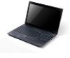
Communication indicator Power button / indicator Keyboard Power indicator Indicates the computer's wireless connectivity device status. Indicates the computer's power status. The left and right buttons function like a computer mouse. 5 English # Icon 2 3 4 5 6 7 ...Touchpad Speaker Microphone 2-in AC mode. Delivers audio output. Turns the computer on and off. Accepts Secure Digital (SD), MultiMediaCard (MMC). Note: Push to remove/install the card. Only one card can operate at any given time. Internal microphone for sound recording. Fully charged: The light shows blue when in...
Communication indicator Power button / indicator Keyboard Power indicator Indicates the computer's wireless connectivity device status. Indicates the computer's power status. The left and right buttons function like a computer mouse. 5 English # Icon 2 3 4 5 6 7 ...Touchpad Speaker Microphone 2-in AC mode. Delivers audio output. Turns the computer on and off. Accepts Secure Digital (SD), MultiMediaCard (MMC). Note: Push to remove/install the card. Only one card can operate at any given time. Internal microphone for sound recording. Fully charged: The light shows blue when in...
Service Guide
Page 7
...of Contents System Specifications 1 Features 1 System Block Diagram 5 Your Acer Notebook tour 6 Front View 6 Closed Front View 7 Closed Rear View 7 Left View 8 Right View 8 Base View 9 Indicators 9 Touchpad Basics 10 Using the Keyboard 11 Lock Keys and embedded numeric keypad 11 Windows Keys 12 Hot ...27 BIOS Setup Utility 27 Navigating the BIOS Utility 27 Aspire 5336 BIOS 28 Information 28 Main 29 Security 30 Boot 33 Exit 34 BIOS Flash Utilities 35 DOS Flash Utility 36 WinFlash Utility 38 Remove HDD/BIOS Password Utilities 39 Machine Disassembly and Replacement 43...
...of Contents System Specifications 1 Features 1 System Block Diagram 5 Your Acer Notebook tour 6 Front View 6 Closed Front View 7 Closed Rear View 7 Left View 8 Right View 8 Base View 9 Indicators 9 Touchpad Basics 10 Using the Keyboard 11 Lock Keys and embedded numeric keypad 11 Windows Keys 12 Hot ...27 BIOS Setup Utility 27 Navigating the BIOS Utility 27 Aspire 5336 BIOS 28 Information 28 Main 29 Security 30 Boot 33 Exit 34 BIOS Flash Utilities 35 DOS Flash Utility 36 WinFlash Utility 38 Remove HDD/BIOS Password Utilities 39 Machine Disassembly and Replacement 43...
Service Guide
Page 8
... Antennas 96 Replacing the Microphone Cable 98 Replacing the LVDS Cable 100 Replacing the LCD Brackets 101 Replacing the LCD/LED Panel 102 Removing the Inverter Board 103 Replacing the Camera Module 105 Replacing the LCD Bezel 106 Main Module Reassembly Procedure 107 Replacing the DC-IN ...129 Replacing the WLAN Module 131 Replacing the DIMM Modules 132 Replacing the Lower Logic Door 133 Replacing the ODD Module 134 Replacing the Keyboard 136 Replacing the SD Dummy Card 137 Replacing the Battery 138 Troubleshooting 139 Common Problems 139 Power On Issue 140 No Display Issue ...
... Antennas 96 Replacing the Microphone Cable 98 Replacing the LVDS Cable 100 Replacing the LCD Brackets 101 Replacing the LCD/LED Panel 102 Removing the Inverter Board 103 Replacing the Camera Module 105 Replacing the LCD Bezel 106 Main Module Reassembly Procedure 107 Replacing the DC-IN ...129 Replacing the WLAN Module 131 Replacing the DIMM Modules 132 Replacing the Lower Logic Door 133 Replacing the ODD Module 134 Replacing the Keyboard 136 Replacing the SD Dummy Card 137 Replacing the Battery 138 Troubleshooting 139 Common Problems 139 Power On Issue 140 No Display Issue ...
Service Guide
Page 55
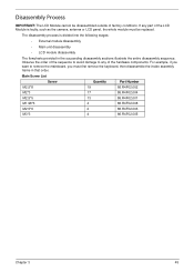
... of factory conditions. The disassembly process is faulty, such as the camera, antenna or LCD panel, the whole module must first remove the keyboard, then disassemble the inside assembly frame in the succeeding disassembly sections illustrate the entire disassembly sequence. Main Screw List Screw Quantity Part ... • LCD module disassembly The flowcharts provided in that order. Observe the order of the sequence to avoid damage to remove the mainboard, you want to any part of the hardware components. Disassembly Process IMPORTANT: The LCD Module cannot be replaced.
... of factory conditions. The disassembly process is faulty, such as the camera, antenna or LCD panel, the whole module must first remove the keyboard, then disassemble the inside assembly frame in the succeeding disassembly sections illustrate the entire disassembly sequence. Main Screw List Screw Quantity Part ... • LCD module disassembly The flowcharts provided in that order. Observe the order of the sequence to avoid damage to remove the mainboard, you want to any part of the hardware components. Disassembly Process IMPORTANT: The LCD Module cannot be replaced.

Service Guide
Page 56
... IMPORTANT: The outside housing and color may vary from system Remove Battery Remove SD Dummy Card Remove Lower Logic Door Remove ODD Remove Keyboard Screw List Step ODD Module ODD Bracket Lower Logic Door WLAN Module HDD Carrier 46 Remove DIMMs Screw M 2.5*8 M2*3 M2.5*8 M2*3 M3*3 Remove WLAN Remove HDD Remove RTC Battery Quantity 1 2 2 1 4 Part No. 86.R4F02.002 86...
... IMPORTANT: The outside housing and color may vary from system Remove Battery Remove SD Dummy Card Remove Lower Logic Door Remove ODD Remove Keyboard Screw List Step ODD Module ODD Bracket Lower Logic Door WLAN Module HDD Carrier 46 Remove DIMMs Screw M 2.5*8 M2*3 M2.5*8 M2*3 M3*3 Remove WLAN Remove HDD Remove RTC Battery Quantity 1 2 2 1 4 Part No. 86.R4F02.002 86...
Service Guide
Page 59
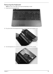
Unlock the six (6) keyboard locks. 2. Chapter 3 49 Pry up the center of the upper cover may vary depending on to the touchpad area to expose the FPC connector. Turn the keyboard over on model. 1. Removing the Keyboard NOTE: The color of the keyboard and rotate it upward away from the upper cover. 3.
Unlock the six (6) keyboard locks. 2. Chapter 3 49 Pry up the center of the upper cover may vary depending on to the touchpad area to expose the FPC connector. Turn the keyboard over on model. 1. Removing the Keyboard NOTE: The color of the keyboard and rotate it upward away from the upper cover. 3.
Service Guide
Page 227
...Device Configuration 31 Power 33 Save and Exit 34 Security 30 System Security 34 Bluetooth Module (Discrete) Removing 72 Board Layout Top View 157 brightness hotkeys 13 C Camera Module Removing 86, 87, 103 Replacing 102, 105, 108 Closed Front View 7 Closed Rear View 7 ...List 163 H Hard Disk Drive Removing 57 Replacing 129 HDTV Switch Failure 151 Hibernation mode hotkey 13 Hot Keys 11 I Indicators 9 Intermittent Problems 152 Internal Microphone Failure 145 Internal Speaker Failure 144 J Jumper and Connector Locations 157 K Keyboard Removing 49 Replacing 136 Keyboard Failure 143 L LCD Bezel ...
...Device Configuration 31 Power 33 Save and Exit 34 Security 30 System Security 34 Bluetooth Module (Discrete) Removing 72 Board Layout Top View 157 brightness hotkeys 13 C Camera Module Removing 86, 87, 103 Replacing 102, 105, 108 Closed Front View 7 Closed Rear View 7 ...List 163 H Hard Disk Drive Removing 57 Replacing 129 HDTV Switch Failure 151 Hibernation mode hotkey 13 Hot Keys 11 I Indicators 9 Intermittent Problems 152 Internal Microphone Failure 145 Internal Speaker Failure 144 J Jumper and Connector Locations 157 K Keyboard Removing 49 Replacing 136 Keyboard Failure 143 L LCD Bezel ...


