Service Guide
Page 8
...Contents Removing the Bluetooth Module 72 Removing the ODD Connector Board 73 Removing the Mainboard 74 Removing the Thermal Module 78 Removing the CPU 79 Removing the LCD Assembly 80 Removing the DC-IN Assembly 83 LCD Module Disassembly Process 84 LCD Module Disassembly Flowchart 84 ...Replacing the LCD Bezel 106 Main Module Reassembly Procedure 107 Replacing the DC-IN Assembly 107 Replacing the LCD Assembly 108 Replacing the CPU 111 Replacing the Thermal Module 112 Replacing the Mainboard 114 Replacing the ODD Connector Board 117 Replacing the Bluetooth Board 118 Replacing ...
...Contents Removing the Bluetooth Module 72 Removing the ODD Connector Board 73 Removing the Mainboard 74 Removing the Thermal Module 78 Removing the CPU 79 Removing the LCD Assembly 80 Removing the DC-IN Assembly 83 LCD Module Disassembly Process 84 LCD Module Disassembly Flowchart 84 ...Replacing the LCD Bezel 106 Main Module Reassembly Procedure 107 Replacing the DC-IN Assembly 107 Replacing the LCD Assembly 108 Replacing the CPU 111 Replacing the Thermal Module 112 Replacing the Mainboard 114 Replacing the ODD Connector Board 117 Replacing the Bluetooth Board 118 Replacing ...
Service Guide
Page 13
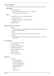
Power Subsystem ACPI 3.0 CPU power management standard: supports Standby and Hibernation power-saving modes Power adapter &#...• ENERGY STAR® Special Keys and Controls • Keyboard • 103-/104-/107-key Acer FineTip keyboard with independent standard numeric keypad, international language support • Touchpad • Multi-gesture touchpad...-45) port • DC-in jack for AC adapter Software • Productivity • Acer Backup Manager • Acer ePower Management • Acer eRecovery Management • Adobe® Flash® Player 10.1 • Adobe® Reader...
Power Subsystem ACPI 3.0 CPU power management standard: supports Standby and Hibernation power-saving modes Power adapter &#...• ENERGY STAR® Special Keys and Controls • Keyboard • 103-/104-/107-key Acer FineTip keyboard with independent standard numeric keypad, international language support • Touchpad • Multi-gesture touchpad...-45) port • DC-in jack for AC adapter Software • Productivity • Acer Backup Manager • Acer ePower Management • Acer eRecovery Management • Adobe® Flash® Player 10.1 • Adobe® Reader...
Service Guide
Page 24
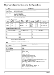
...size 2 MB Features Support ISIPP Support Acer UI Support multi-boot Suspend to RAM (S3)/Disk (S4) Various hot-keys for system control Support SMBUS 3.0, PCI3.0 ACPI 3.0b compliance with Intel Speed Step Support C1, C2, C3, C4 and S3, S4 for mobile CPU DMI utility for BIOS serial number configurable...Bus Speed 800MHz T3500 21.G 2 800MHz Cache Size 1M 1M Package MicroFCPGA MicroFCPGA Core Voltage 1.0V 1.2V 0.8V1.25V Acer PN KC.N0001.900 KC.35001.CMT CPU Fan True Value Table (TJ105) CPU Temperature Fan Speed (RPM) 50 2300 55 2500 60 2700 65 3000 85 3300 SPL Spec (dBA) 28 31...
...size 2 MB Features Support ISIPP Support Acer UI Support multi-boot Suspend to RAM (S3)/Disk (S4) Various hot-keys for system control Support SMBUS 3.0, PCI3.0 ACPI 3.0b compliance with Intel Speed Step Support C1, C2, C3, C4 and S3, S4 for mobile CPU DMI utility for BIOS serial number configurable...Bus Speed 800MHz T3500 21.G 2 800MHz Cache Size 1M 1M Package MicroFCPGA MicroFCPGA Core Voltage 1.0V 1.2V 0.8V1.25V Acer PN KC.N0001.900 KC.35001.CMT CPU Fan True Value Table (TJ105) CPU Temperature Fan Speed (RPM) 50 2300 55 2500 60 2700 65 3000 85 3300 SPL Spec (dBA) 28 31...

Service Guide
Page 35
... in the system are turned off completely. Battery full • Amber blinking - Individual devices such as the CPU and hard disk may be power managed in low power state Discharging • Amber and blinking - CPU set power down VGA suspend PCMCIA suspend Audio power down Hard Disk power down CD-ROM power...
... in the system are turned off completely. Battery full • Amber blinking - Individual devices such as the CPU and hard disk may be power managed in low power state Discharging • Amber and blinking - CPU set power down VGA suspend PCMCIA suspend Audio power down Hard Disk power down CD-ROM power...
Service Guide
Page 38
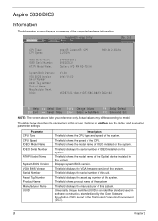
... tag number of the system. Actual values may differ according to model. InsydeH20 Setup Utility Information Main Security Boot Exit Rev. 3.5 CPU Type: CPU Speed: IDEO Model Name: IDEO Serial Number: ATAPI Model Name: System BIOS Version: VGA BIOS Version: Serial Number Asset Tag Number...Number Asset Tag Number Product Name Manufacturer Name UUID Description This field shows the CPU type and speed of the computer hardware information. This field shows the model name of this unit. Aspire 5336 BIOS Information The Information screen displays a summary of the system. Settings in the...
... tag number of the system. Actual values may differ according to model. InsydeH20 Setup Utility Information Main Security Boot Exit Rev. 3.5 CPU Type: CPU Speed: IDEO Model Name: IDEO Serial Number: ATAPI Model Name: System BIOS Version: VGA BIOS Version: Serial Number Asset Tag Number...Number Asset Tag Number Product Name Manufacturer Name UUID Description This field shows the CPU type and speed of the computer hardware information. This field shows the model name of this unit. Aspire 5336 BIOS Information The Information screen displays a summary of the system. Settings in the...
Service Guide
Page 70
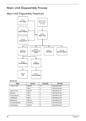
... Remove Touchpad FFC Remove Upper Cover Remove Mainboard Remove ODD Connector Board Remove USB Board Remove Bluetooth Module Remove Thermal Module Remove LCD Module Remove CPU Remove DC-IN Assembly Screw List Step Lower Cover Upper Cover Speaker Power Board USB Board Mainboard Thermal Module LCD Module Screw M2.5*8 M2*3 M2...
... Remove Touchpad FFC Remove Upper Cover Remove Mainboard Remove ODD Connector Board Remove USB Board Remove Bluetooth Module Remove Thermal Module Remove LCD Module Remove CPU Remove DC-IN Assembly Screw List Step Lower Cover Upper Cover Speaker Power Board USB Board Mainboard Thermal Module LCD Module Screw M2.5*8 M2*3 M2...
Service Guide
Page 89
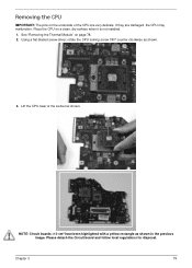
Please detach the Circuit board and follow local regulations for disposal. If they are very delicate. Lift the CPU clear of the CPU are damaged, the CPU may malfunction. Chapter 3 79 Using a flat-bladed screw driver, rotate the CPU locking screw 180° counter-clockwise as shown. NOTE: Circuit boards >10 cm² have been... with a yellow rectangle as shown in the previous image. See "Removing the Thermal Module" on a clean, dry surface when it is not installed. 1. Removing the CPU IMPORTANT: The pins on the underside of the socket as shown. 3. Place the...
Please detach the Circuit board and follow local regulations for disposal. If they are very delicate. Lift the CPU clear of the CPU are damaged, the CPU may malfunction. Chapter 3 79 Using a flat-bladed screw driver, rotate the CPU locking screw 180° counter-clockwise as shown. NOTE: Circuit boards >10 cm² have been... with a yellow rectangle as shown in the previous image. See "Removing the Thermal Module" on a clean, dry surface when it is not installed. 1. Removing the CPU IMPORTANT: The pins on the underside of the socket as shown. 3. Place the...
Service Guide
Page 121
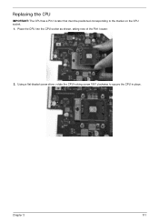
Replacing the CPU IMPORTANT: The CPU has a Pin1 locator that must be positioned corresponding to secure the CPU in place. Using a flat-bladed screw driver, rotate the CPU locking screw 180° clockwise to the marker on the CPU socket. 1. Chapter 3 111 Place the CPU into the CPU socket as shown, taking note of the Pin1 locator. 2.
Replacing the CPU IMPORTANT: The CPU has a Pin1 locator that must be positioned corresponding to secure the CPU in place. Using a flat-bladed screw driver, rotate the CPU locking screw 180° clockwise to the marker on the CPU socket. 1. Chapter 3 111 Place the CPU into the CPU socket as shown, taking note of the Pin1 locator. 2.

Service Guide
Page 122
... suitable thermal grease and ensure all traces of the thermal module is sufficient. 3. Replace the four (4) securing screws (in numerical order from the CPU using a lint-free cloth or cotton swab and Isopropyl Alcohol or other approved cleaning agent. 2. Keep the module as level as possible to secure... 2 3 4 1 Step Thermal Module Size M1.98*3 (red callouts) 112 Quantity 4 . Apply a small amount of thermal grease to the center of the CPU-there is no need to spread the grease manually, the force used during the installation of thermal grease from screw 1 to screw 4) to spread the...
... suitable thermal grease and ensure all traces of the thermal module is sufficient. 3. Replace the four (4) securing screws (in numerical order from the CPU using a lint-free cloth or cotton swab and Isopropyl Alcohol or other approved cleaning agent. 2. Keep the module as level as possible to secure... 2 3 4 1 Step Thermal Module Size M1.98*3 (red callouts) 112 Quantity 4 . Apply a small amount of thermal grease to the center of the CPU-there is no need to spread the grease manually, the force used during the installation of thermal grease from screw 1 to screw 4) to spread the...

Service Guide
Page 163
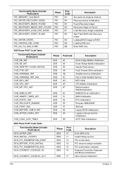
... Phase SEC SEC_BEFORE_MICROCODE_PATCH SEC_AFTER_MICROCODE_PATCH SEC_SETUP_CAR_OK SEC_GO_TO_SECSTARTUP SEC_GO_TO_PEICORE SEC SEC SEC SEC SEC Post Code 1 2 3 7 9 0A Description CPU power on and switch to use Memory Chapter 4 153 Memory Initial for Crisis Recovery Simple Memory test Start to Protected mode Patching...Post Code 70 71 72 73 74 75 76 77 78 79 7A 7E 7F 80 82 Description Super I/O Initialization CPU Early Initialization Multi-processor Early Initial HyperTransport Initialization PCIE MMIO BAR Initialization North Bridge Early Initialization South Bridge Early Initialization ...
... Phase SEC SEC_BEFORE_MICROCODE_PATCH SEC_AFTER_MICROCODE_PATCH SEC_SETUP_CAR_OK SEC_GO_TO_SECSTARTUP SEC_GO_TO_PEICORE SEC SEC SEC SEC SEC Post Code 1 2 3 7 9 0A Description CPU power on and switch to use Memory Chapter 4 153 Memory Initial for Crisis Recovery Simple Memory test Start to Protected mode Patching...Post Code 70 71 72 73 74 75 76 77 78 79 7A 7E 7F 80 82 Description Super I/O Initialization CPU Early Initialization Multi-processor Early Initial HyperTransport Initialization PCIE MMIO BAR Initialization North Bridge Early Initialization South Bridge Early Initialization ...
Service Guide
Page 164
... North bridge Middle initialization South Bridge Middle initialization Identify Flash device Fault Tolerant Write verification Variable Service initialization Fail to initial Variable Service MTC Initial CPU Middle Initialization Multi-processor MiddleInitialization SMBUS Driver Initialization 8259 Initialization RTC Initialization Relocate SMM BASE SMI test Legacy BIOS Initialization Legacy interrupt function Initialization ACPI...
... North bridge Middle initialization South Bridge Middle initialization Identify Flash device Fault Tolerant Write verification Variable Service initialization Fail to initial Variable Service MTC Initial CPU Middle Initialization Multi-processor MiddleInitialization SMBUS Driver Initialization 8259 Initialization RTC Initialization Relocate SMM BASE SMI test Legacy BIOS Initialization Legacy interrupt function Initialization ACPI...
Service Guide
Page 168
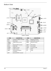
Bottom View PJP2 JCPU1 PJP1 U23 U11 JFAN1 JCRT1 JBATT1 JMINI1 JHDD1 JBT1 ITEM PJP2 PJP1 JDIMM1 / JDIMM2 JCRT1 JRJ45 JHDMI1 JUSB1 JMIC1 JHP1 JDIMM1/JDIMM2 DESCRIPTION Connect to battery connector DC-IN jack DDR3 memory socket ITEM JBT1 JHDD1 JMINI1 DESCRIPTION Bluetooth connector SATA HDD connector WLAN connector External CRT connector RJ45 LAN HDMI connector USB connector External microphone connector External SPDIF connector JBATT1 JCPU1 JFAN1 U23 U11 RTC battery CPU socket Connect to FAN MCH ICH9 JRJ45 JHDMI1 JUSB1 JMIC1 JHP1 158 Chapter 3
Bottom View PJP2 JCPU1 PJP1 U23 U11 JFAN1 JCRT1 JBATT1 JMINI1 JHDD1 JBT1 ITEM PJP2 PJP1 JDIMM1 / JDIMM2 JCRT1 JRJ45 JHDMI1 JUSB1 JMIC1 JHP1 JDIMM1/JDIMM2 DESCRIPTION Connect to battery connector DC-IN jack DDR3 memory socket ITEM JBT1 JHDD1 JMINI1 DESCRIPTION Bluetooth connector SATA HDD connector WLAN connector External CRT connector RJ45 LAN HDMI connector USB connector External microphone connector External SPDIF connector JBATT1 JCPU1 JFAN1 U23 U11 RTC battery CPU socket Connect to FAN MCH ICH9 JRJ45 JHDMI1 JUSB1 JMIC1 JHP1 158 Chapter 3

Service Guide
Page 180
... UPPER CASE ASSY, INCL.TP - Category Description CASE/COVER/BRACKET ASSEMBLY UPPER CASE ASSY, INCL.TP - UMA, RED UPPER CASE ASSY, INCL.TP - UMA, BROWN Acer Part No. 60.R4F02.001 60.R4M02.001 60.R4L02.001 LOWER CASE-UMA 60.R4F02.002 UNILOAD DOOR-UMA HDD CARRIER-UMA 42.R4F02....001 33.R4F02.001 CPU/PROCESSOR HDD/HARD DISK DRIVE CPU INTEL CELERON 900 PGA 2.2G 1M 800 35W CPU INTEL CELERON T3500 PGA 2.1G 1M 800 35W CPU INTEL PENTIUM DUAL-CORE T4500 2.3G 1M 800 KC.N0001.900 KC.35001.CMT...
... UPPER CASE ASSY, INCL.TP - Category Description CASE/COVER/BRACKET ASSEMBLY UPPER CASE ASSY, INCL.TP - UMA, RED UPPER CASE ASSY, INCL.TP - UMA, BROWN Acer Part No. 60.R4F02.001 60.R4M02.001 60.R4L02.001 LOWER CASE-UMA 60.R4F02.002 UNILOAD DOOR-UMA HDD CARRIER-UMA 42.R4F02....001 33.R4F02.001 CPU/PROCESSOR HDD/HARD DISK DRIVE CPU INTEL CELERON 900 PGA 2.2G 1M 800 35W CPU INTEL CELERON T3500 PGA 2.1G 1M 800 35W CPU INTEL PENTIUM DUAL-CORE T4500 2.3G 1M 800 KC.N0001.900 KC.35001.CMT...
Service Guide
Page 197
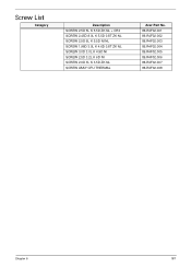
Screw List Category Description SCREW 2.5D 5L K 5.5D ZK NL + CR3 SCREW 2.45D 8.0L K 5.5D 0.8T ZK NL SCREW 2.5D 6L K 5.5D NI NL SCREW 1.98D 3.0L K 4.6D 0.8T ZK NL SCREW 3.0D 3.0L K 4.9D NI SCREW 2.5D 3.2L K 6D NI SCREW 2.0D 3L K 3.5D ZK NL SCREW ASSY CPU THERMAL Acer Part No. 86.R4F02.001 86.R4F02.002 86.R4F02.003 86.R4F02.004 86.R4F02.005 86.R4F02.006 86.R4F02.007 86.R4F02.008 Chapter 6 187
Screw List Category Description SCREW 2.5D 5L K 5.5D ZK NL + CR3 SCREW 2.45D 8.0L K 5.5D 0.8T ZK NL SCREW 2.5D 6L K 5.5D NI NL SCREW 1.98D 3.0L K 4.6D 0.8T ZK NL SCREW 3.0D 3.0L K 4.9D NI SCREW 2.5D 3.2L K 6D NI SCREW 2.0D 3L K 3.5D ZK NL SCREW ASSY CPU THERMAL Acer Part No. 86.R4F02.001 86.R4F02.002 86.R4F02.003 86.R4F02.004 86.R4F02.005 86.R4F02.006 86.R4F02.007 86.R4F02.008 Chapter 6 187

Service Guide
Page 221
... SEAGATE N250GB5.4KS SEAGATE N320GB5.4KS SEAGATE N500GB5.4KS TOSHIBA N160GB5.4KS Description Foxconn Bluetooth ATH AR3011 (BT3.0) Foxconn Bluetooth BRM 2070 (T77H114.01) BT 3.0 Acer Part No BH.21100.009 BH.21100.010 Chicony 1.3M CH9665SN (CNF9157) Liteon 1.3M LT9665AL (09P2SF119) Liteon 1.3M LT6AASP(09P2BF127) Suyin 1.3M SY9665SN AM.....067 AM.21400.069 AM.21400.070 AM.21400.068 2-in-1 card reader CR.21500.030 CPU Intel Celeron 900 PGA 2.2G 1M 800 35W CPU Intel Celeron T3500 PGA 2.1G 1M 800 35W CPU Intel Pentium Dual-Core T4500 2.3G 1M 800 KC.N0001.900 KC.35001.CMT KC.45001.DTP...
... SEAGATE N250GB5.4KS SEAGATE N320GB5.4KS SEAGATE N500GB5.4KS TOSHIBA N160GB5.4KS Description Foxconn Bluetooth ATH AR3011 (BT3.0) Foxconn Bluetooth BRM 2070 (T77H114.01) BT 3.0 Acer Part No BH.21100.009 BH.21100.010 Chicony 1.3M CH9665SN (CNF9157) Liteon 1.3M LT9665AL (09P2SF119) Liteon 1.3M LT6AASP(09P2BF127) Suyin 1.3M SY9665SN AM.....067 AM.21400.069 AM.21400.070 AM.21400.068 2-in-1 card reader CR.21500.030 CPU Intel Celeron 900 PGA 2.2G 1M 800 35W CPU Intel Celeron T3500 PGA 2.1G 1M 800 35W CPU Intel Pentium Dual-Core T4500 2.3G 1M 800 KC.N0001.900 KC.35001.CMT KC.45001.DTP...
Service Guide
Page 227
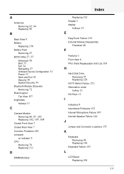
... brightness hotkeys 13 C Camera Module Removing 86, 87, 103 Replacing 102, 105, 108 Closed Front View 7 Closed Rear View 7 Common Problems 140 computer on indicator 9 CPU Removing 79 Replacing 111 D DIMM Modules Index Replacing 132 Display 5 display hotkeys 13 E EasyTouch Failure 150 External Module Disassembly Flowchart 46 F Features 1 Front View 6 FRU...
... brightness hotkeys 13 C Camera Module Removing 86, 87, 103 Replacing 102, 105, 108 Closed Front View 7 Closed Rear View 7 Common Problems 140 computer on indicator 9 CPU Removing 79 Replacing 111 D DIMM Modules Index Replacing 132 Display 5 display hotkeys 13 E EasyTouch Failure 150 External Module Disassembly Flowchart 46 F Features 1 Front View 6 FRU...

