Service Guide
Page 7
Table of Contents System Specifications 1 Features 1 System Block Diagram 5 Your Acer Notebook tour 6 Front View 6 Closed Front View 7 Closed Rear View 7 Left View 8 Right View 8 Base View 9 Indicators 9 Touchpad Basics 10 Using the Keyboard 11 Lock ... 12 Hot Keys 13 Hardware Specifications and Configurations 14 System Utilities 27 BIOS Setup Utility 27 Navigating the BIOS Utility 27 Aspire 5336 BIOS 28 Information 28 Main 29 Security 30 Boot 33 Exit 34 BIOS Flash Utilities 35 DOS Flash Utility 36 WinFlash Utility 38 Remove HDD/BIOS Password Utilities 39 Machine...
Table of Contents System Specifications 1 Features 1 System Block Diagram 5 Your Acer Notebook tour 6 Front View 6 Closed Front View 7 Closed Rear View 7 Left View 8 Right View 8 Base View 9 Indicators 9 Touchpad Basics 10 Using the Keyboard 11 Lock ... 12 Hot Keys 13 Hardware Specifications and Configurations 14 System Utilities 27 BIOS Setup Utility 27 Navigating the BIOS Utility 27 Aspire 5336 BIOS 28 Information 28 Main 29 Security 30 Boot 33 Exit 34 BIOS Flash Utilities 35 DOS Flash Utility 36 WinFlash Utility 38 Remove HDD/BIOS Password Utilities 39 Machine...
Service Guide
Page 24
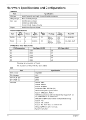
...shut down at 90C Item Specification BIOS vendor InsydeH20 BIOS Version V1.0 BIOS ROM type Flash BIOS ROM size 2 MB Features Support ISIPP Support Acer UI Support multi-boot Suspend to RAM (S3)/Disk (S4) Various hot-keys for system control Support SMBUS 3.0, PCI3.0 ACPI 3.0b compliance with Intel Speed ...Cores CM900 2.2G 2 Bus Speed 800MHz T3500 21.G 2 800MHz Cache Size 1M 1M Package MicroFCPGA MicroFCPGA Core Voltage 1.0V 1.2V 0.8V1.25V Acer PN KC.N0001.900 KC.35001.CMT CPU Fan True Value Table (TJ105) CPU Temperature Fan Speed (RPM) 50 2300 55 2500 60 2700 ...
...shut down at 90C Item Specification BIOS vendor InsydeH20 BIOS Version V1.0 BIOS ROM type Flash BIOS ROM size 2 MB Features Support ISIPP Support Acer UI Support multi-boot Suspend to RAM (S3)/Disk (S4) Various hot-keys for system control Support SMBUS 3.0, PCI3.0 ACPI 3.0b compliance with Intel Speed ...Cores CM900 2.2G 2 Bus Speed 800MHz T3500 21.G 2 800MHz Cache Size 1M 1M Package MicroFCPGA MicroFCPGA Core Voltage 1.0V 1.2V 0.8V1.25V Acer PN KC.N0001.900 KC.35001.CMT CPU Fan True Value Table (TJ105) CPU Temperature Fan Speed (RPM) 50 2300 55 2500 60 2700 ...
Service Guide
Page 29
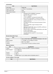
...• Receive side scaling (RSS) for multicore processors • Complies with IEEE 802.3, 802.3u, 802.3ab, and 802.1p • Supports iSCSI boot • IPv4 and IPv6 large send off load and checksum off load (LSO/TCO) • Wake on LAN (WOL) support meeting the ACPI requirements... • Statistics for SNMP MIB II, Ethernet-like MIB, and Ethernet MIB (IEEE 802.3z, Clause 30) • Self-boot feature, utilizing smaller EEPROM size with ability to use on-chip memory • PCI Express® CLKREQ support • Integrated switching regulator for improved ...
...• Receive side scaling (RSS) for multicore processors • Complies with IEEE 802.3, 802.3u, 802.3ab, and 802.1p • Supports iSCSI boot • IPv4 and IPv6 large send off load and checksum off load (LSO/TCO) • Wake on LAN (WOL) support meeting the ACPI requirements... • Statistics for SNMP MIB II, Ethernet-like MIB, and Ethernet MIB (IEEE 802.3z, Clause 30) • Self-boot feature, utilizing smaller EEPROM size with ability to use on-chip memory • PCI Express® CLKREQ support • Integrated switching regulator for improved ...
Service Guide
Page 37
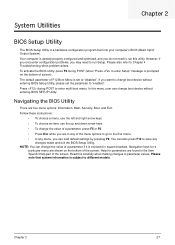
... a hardware configuration program built into your computer's BIOS (Basic Input/ Output System). Please also refer to parameter values. You can change boot device without entering BIOS Setup Utility, please set to "disabled". Help for a particular menu are shown on the bottom of F12... menu, use the left and right arrow keys. • To choose an item, use the up and down arrow keys. • To change boot device without entering BIOS SETUP Utility. Chapter 2 27 System Utilities Chapter 2 BIOS Setup Utility The BIOS Setup Utility is subject to different models. Navigating the...
... a hardware configuration program built into your computer's BIOS (Basic Input/ Output System). Please also refer to parameter values. You can change boot device without entering BIOS Setup Utility, please set to "disabled". Help for a particular menu are shown on the bottom of F12... menu, use the left and right arrow keys. • To choose an item, use the up and down arrow keys. • To change boot device without entering BIOS SETUP Utility. Chapter 2 27 System Utilities Chapter 2 BIOS Setup Utility The BIOS Setup Utility is subject to different models. Navigating the...
Service Guide
Page 38
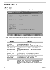
...the speed of the system. This field displays the serial number of IDEO installed on the system. InsydeH20 Setup Utility Information Main Security Boot Exit Rev. 3.5 CPU Type: CPU Speed: IDEO Model Name: IDEO Serial Number: ATAPI Model Name: System BIOS Version: VGA ...This field displays the manufacturer of the system. This field shows the model name of the Distributed Computing Environment (DCE). 28 Chapter 2 Aspire 5336 BIOS Information The Information screen displays a summary of this system. Settings in software construction, standardized by the Open Software Foundation (OSF)...
...the speed of the system. This field displays the serial number of IDEO installed on the system. InsydeH20 Setup Utility Information Main Security Boot Exit Rev. 3.5 CPU Type: CPU Speed: IDEO Model Name: IDEO Serial Number: ATAPI Model Name: System BIOS Version: VGA ...This field displays the manufacturer of the system. This field shows the model name of the Distributed Computing Environment (DCE). 28 Chapter 2 Aspire 5336 BIOS Information The Information screen displays a summary of this system. Settings in software construction, standardized by the Open Software Foundation (OSF)...
Service Guide
Page 39
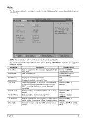
... is for your reference only. Enables, disables D2D Recovery function. Parameter System Time System Date Total Memory Video Memory Quiet Boot Network Boot F12 Boot Menu D2D Recovery SATA Mode Description Sets the system time. Displays the total memory available. Actual values may differ. F1 Help... Disabled Option: Enabled or Disabled Option: Enabled or Disabled Option: AHCI Mode or IDE Mode Chapter 2 29 Enables, disables the system boot from 0 to factory defaults. Sets the system date. The table below describes the parameters in this screen. Main The Main screen allows...
... is for your reference only. Enables, disables D2D Recovery function. Parameter System Time System Date Total Memory Video Memory Quiet Boot Network Boot F12 Boot Menu D2D Recovery SATA Mode Description Sets the system time. Displays the total memory available. Actual values may differ. F1 Help... Disabled Option: Enabled or Disabled Option: Enabled or Disabled Option: AHCI Mode or IDE Mode Chapter 2 29 Enables, disables the system boot from 0 to factory defaults. Sets the system date. The table below describes the parameters in this screen. Main The Main screen allows...
Service Guide
Page 40
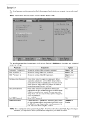
... (TPM). CAUTION: It may have to return your notebook computer to your computer from unauthorized use. InsydeH20 Setup Utility Information Main Security Boot Exit Supervisor Password Is: User Password Is: HDD Password Is: Set Supervisor Password Set User Password Set HDD Password Clear Clear Frozen Rev...or Change the password and the length of parameters except the date and time. Settings in order for the computer to finish booting up. Take care when using this password protects the BIOS Setup Utility from unauthorized access. Security The Security screen contains parameters ...
... (TPM). CAUTION: It may have to return your notebook computer to your computer from unauthorized use. InsydeH20 Setup Utility Information Main Security Boot Exit Supervisor Password Is: User Password Is: HDD Password Is: Set Supervisor Password Set User Password Set HDD Password Clear Clear Frozen Rev...or Change the password and the length of parameters except the date and time. Settings in order for the computer to finish booting up. Take care when using this password protects the BIOS Setup Utility from unauthorized access. Security The Security screen contains parameters ...
Service Guide
Page 41
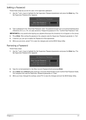
... Password" field. Type a password in the "Confirm New Password" field. IMPORTANT:Be very careful when typing your password because the characters do not appear on Boot parameter. 5. Use the ↑ and ↓ keys to "Set". 4. The Set Supervisor Password box appears: Set Supervisor Password Enter New Password [ ] Confirm New Password [ ] 2. After...
... Password" field. Type a password in the "Confirm New Password" field. IMPORTANT:Be very careful when typing your password because the characters do not appear on Boot parameter. 5. Use the ↑ and ↓ keys to "Set". 4. The Set Supervisor Password box appears: Set Supervisor Password Enter New Password [ ] Confirm New Password [ ] 2. After...
Service Guide
Page 42
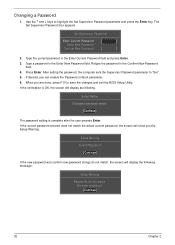
... user presses Enter. If the current password entered does not match the actual current password, the screen will show you can enable the Password on Boot parameter. 6. Changing a Password 1. Set Supervisor Password Enter Current Password [ ] Enter New Password [ ] Confirm New Password [ ] 2. If desired, you the Setup Warning. Setup Notice Changes have...
... user presses Enter. If the current password entered does not match the actual current password, the screen will show you can enable the Password on Boot parameter. 6. Changing a Password 1. Set Supervisor Password Enter Current Password [ ] Enter New Password [ ] Confirm New Password [ ] 2. If desired, you the Setup Warning. Setup Notice Changes have...

Service Guide
Page 43
... devices includes the USB diskette drives, the onboard hard disk drive and the DVD drive in the module bay. IDE1 : HL-DT-STDVDRAM GT32N 3. Select Boot menu to select specific devices to escape the menu F1 Help ESC Exit Select Item F5/F6 Change Values F9 Setup Default Select Menu Enter... Select SubMenu F10 Save and Exit Chapter 2 33 USB FDD : 4. Press to support boot. USB CDROM: Use < > or < > to select a device, then press to move it down the list, or to load the operating system...
... devices includes the USB diskette drives, the onboard hard disk drive and the DVD drive in the module bay. IDE1 : HL-DT-STDVDRAM GT32N 3. Select Boot menu to select specific devices to escape the menu F1 Help ESC Exit Select Item F5/F6 Change Values F9 Setup Default Select Menu Enter... Select SubMenu F10 Save and Exit Chapter 2 33 USB FDD : 4. Press to support boot. USB CDROM: Use < > or < > to select a device, then press to move it down the list, or to load the operating system...
Service Guide
Page 44
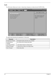
Information Main InsydeH20 Setup Utility Security Boot Exit Rev. 3.5 Exit Saving Changes Exit Discarding Changes Load Setup Defaults Discard Changes Save Changes Item Specific Help Exit System Setup and save your changes ...
Information Main InsydeH20 Setup Utility Security Boot Exit Rev. 3.5 Exit Saving Changes Exit Discarding Changes Load Setup Defaults Discard Changes Save Changes Item Specific Help Exit System Setup and save your changes ...
Service Guide
Page 45
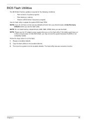
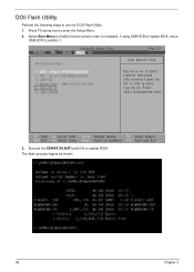
NOTE: Please use the AC adaptor power supply when you may not boot the system because the BIOS is required for the following conditions: • New versions of system programs • New features or options • Restore a BIOS ... use the flash utility. Chapter 2 35 Copy the flash utilities to update the system BIOS flash ROM. The flash utility has auto-execution function. Then boot the system from the bootable diskette. If the battery pack does not contain enough power to run the flash utility.
NOTE: Please use the AC adaptor power supply when you may not boot the system because the BIOS is required for the following conditions: • New versions of system programs • New features or options • Restore a BIOS ... use the flash utility. Chapter 2 35 Copy the flash utilities to update the system BIOS flash ROM. The flash utility has auto-execution function. Then boot the system from the bootable diskette. If the battery pack does not contain enough power to run the flash utility.
Service Guide
Page 46
... F5/F6 Change Values F9 Setup Default Select Menu Enter Select SubMenu F10 Save and Exit 3. IDEO : Hitachi HTS545032B9A300 2. InsydeH20 Setup Utility Information Main Security Boot Exit Boot priority order: Rev. 3.5 Item Specific Help 1. USB HDD : 6. USB FDD : 4. Press to update BIOS. IDE1 : HL-DT-STDVDRAM GT32N 3. USB CDROM: ... up the list. The flash process begins as shown. 36 Chapter 2 Press F2 during boot to move USB HDD to use the DOS Flash Utility: 1. Select Boot Menu to modify the boot priority order, for example, if using USB HDD to Update BIOS, move it down the...
... F5/F6 Change Values F9 Setup Default Select Menu Enter Select SubMenu F10 Save and Exit 3. IDEO : Hitachi HTS545032B9A300 2. InsydeH20 Setup Utility Information Main Security Boot Exit Boot priority order: Rev. 3.5 Item Specific Help 1. USB HDD : 6. USB FDD : 4. Press to update BIOS. IDE1 : HL-DT-STDVDRAM GT32N 3. USB CDROM: ... up the list. The flash process begins as shown. 36 Chapter 2 Press F2 during boot to move USB HDD to use the DOS Flash Utility: 1. Select Boot Menu to modify the boot priority order, for example, if using USB HDD to Update BIOS, move it down the...
Service Guide
Page 51
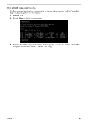
Chapter 2 41 Execute BS.exe to be changed without accessing the BIOS. Using Boot Sequence Selector The Boot Sequence Selector allows the boot order to display the usage screen. 3. Select the desired boot sequence by entering the corresponding sequence. To use Boot Sequence Selector, perform the following steps: 1. Enter into DOS. 2. For example, enter BS 2 to change the boot sequence to HDD | CD ROM | LAN | Floppy.
Chapter 2 41 Execute BS.exe to be changed without accessing the BIOS. Using Boot Sequence Selector The Boot Sequence Selector allows the boot order to display the usage screen. 3. Select the desired boot sequence by entering the corresponding sequence. To use Boot Sequence Selector, perform the following steps: 1. Enter into DOS. 2. For example, enter BS 2 to change the boot sequence to HDD | CD ROM | LAN | Floppy.
Service Guide
Page 52
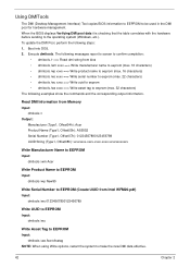
... Serial Number (Type1, Offset07h): 01234567890123456789 UUID String (Type1, Offset08h): xxxxxxxx-xxxx-xxxx-xxxx-xxxxxxxxxxxx Write Manufacturer Name to EEPROM Input: dmitools /wm Acer Write Product Name to EEPROM Input: dmitools /wp New95 Write Serial Number to EEPROM (Create UUID from bios • dmitools /wm xxxx ==> Write...dmitools /wa Acet Asstag NOTE: When using Write options, restart the system to be used in the DMI pool for hardware management. Boot into DOS. 2. When the BIOS displays Verifying DMI pool data it is checking that the table correlates with the hardware before sending to...
... Serial Number (Type1, Offset07h): 01234567890123456789 UUID String (Type1, Offset08h): xxxxxxxx-xxxx-xxxx-xxxx-xxxxxxxxxxxx Write Manufacturer Name to EEPROM Input: dmitools /wm Acer Write Product Name to EEPROM Input: dmitools /wp New95 Write Serial Number to EEPROM (Create UUID from bios • dmitools /wm xxxx ==> Write...dmitools /wa Acet Asstag NOTE: When using Write options, restart the system to be used in the DMI pool for hardware management. Boot into DOS. 2. When the BIOS displays Verifying DMI pool data it is checking that the table correlates with the hardware before sending to...
Service Guide
Page 150
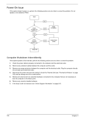
... protectors between the computer and the outlet. 3. Power On Issue If the system doesn't power on page 150) and fan airways are not necessary to boot the computer to correct the problem.
... protectors between the computer and the outlet. 3. Power On Issue If the system doesn't power on page 150) and fan airways are not necessary to boot the computer to correct the problem.
Service Guide
Page 151
.... 1. On this model). Drain any memory cards and CD/DVD discs. Reseat the memory modules. 7. Reconnect the power and reboot the computer. 4. If the computer boots correctly, add the devices one by removing the power cable and battery and holding down the power button for specific model procedures. 2. If the Issue...
.... 1. On this model). Drain any memory cards and CD/DVD discs. Reseat the memory modules. 7. Reconnect the power and reboot the computer. 4. If the computer boots correctly, add the devices one by removing the power cable and battery and holding down the power button for specific model procedures. 2. If the Issue...
Service Guide
Page 156
...9. Restore system and file settings from a command prompt. Disconnect all cables and jumpers on the HDD and ODD are set as the first boot device on page 45. 146 Chapter 4 e. NOTE: Click Load Drivers if controller drives are correct and that CD/DVD drive is virus free... to the operating system DVD. If the issue is discovered, follow the onscreen information to enter the BIOS Utility. See "Disassembly Process" on the Boot menu. 6. Run the Windows Vista Startup Repair Utility: a. When prompted, press any recently added hardware and associated software. 8. c. Click Next....
...9. Restore system and file settings from a command prompt. Disconnect all cables and jumpers on the HDD and ODD are set as the first boot device on page 45. 146 Chapter 4 e. NOTE: Click Load Drivers if controller drives are correct and that CD/DVD drive is virus free... to the operating system DVD. If the issue is discovered, follow the onscreen information to enter the BIOS Utility. See "Disassembly Process" on the Boot menu. 6. Run the Windows Vista Startup Repair Utility: a. When prompted, press any recently added hardware and associated software. 8. c. Click Next....

Service Guide
Page 163
... Start to Protected mode Patching CPU microcode Setup Cache as RAM Cache as RAM test Setup BIOS ROM cache Enter Boot Firmware Volume PEI Phase POST Code Table: Functionality Name (Include\ PostCode.h) PEI_SIO_INIT PEI_CPU_REG_INIT PEI_CPU_AP_INIT PEI_CPU_HT_RESET PEI_PCIE_MMIO_INIT PEI_NB_REG_INIT PEI_SB_REG_INIT... Initialization South Bridge Early Initialization PCIE Training TPM Initialization SMBUS Early Initialization Clock Generator Initialization Memory Initial for Normal boot. Post Codes These tables describe the POST codes and descriptions during the POST. Post Code Range SEC PEI ...
... Start to Protected mode Patching CPU microcode Setup Cache as RAM Cache as RAM test Setup BIOS ROM cache Enter Boot Firmware Volume PEI Phase POST Code Table: Functionality Name (Include\ PostCode.h) PEI_SIO_INIT PEI_CPU_REG_INIT PEI_CPU_AP_INIT PEI_CPU_HT_RESET PEI_PCIE_MMIO_INIT PEI_NB_REG_INIT PEI_SB_REG_INIT... Initialization South Bridge Early Initialization PCIE Training TPM Initialization SMBUS Early Initialization Clock Generator Initialization Memory Initial for Normal boot. Post Codes These tables describe the POST codes and descriptions during the POST. Post Code Range SEC PEI ...

Service Guide
Page 165
... POST_BDS_ENTER_INT19 POST_BDS_JUMP_BOOT_SECTOR Phase POST_BDS POST_BDS POST_BDS POST_BDS Post Code F9 FB FD FE Description No Boot Device UEFI Boot Start Image Legacy 16 boot entry Try to Boot Legacy OS. Ready to Boot with INT 19 Chapter 4 155 Fast Recovery Start Flash. Functionality Name (Include\ PostCode...initialization Serial device initialization IDE device initialization AHCI device initialization Dispatch option ROMs Get boot device information End of boot selection Enter Setup Menu Enter Boot manager Try to boot system to OS Shadow Misc Option ROM Save S3 resume required data in ...
... POST_BDS_ENTER_INT19 POST_BDS_JUMP_BOOT_SECTOR Phase POST_BDS POST_BDS POST_BDS POST_BDS Post Code F9 FB FD FE Description No Boot Device UEFI Boot Start Image Legacy 16 boot entry Try to Boot Legacy OS. Ready to Boot with INT 19 Chapter 4 155 Fast Recovery Start Flash. Functionality Name (Include\ PostCode...initialization Serial device initialization IDE device initialization AHCI device initialization Dispatch option ROMs Get boot device information End of boot selection Enter Setup Menu Enter Boot manager Try to boot system to OS Shadow Misc Option ROM Save S3 resume required data in ...


