Service Guide
Page 7
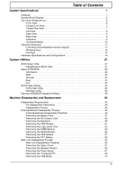
... System Specifications 1 Features 1 System Block Diagram 5 Your Acer Notebook tour 6 Front View 6 Closed Front View 7 ...BIOS Setup Utility 27 Navigating the BIOS Utility 27 Aspire 5336 BIOS 28 Information 28 Main 29 Security 30 Boot 33 Exit 34 BIOS Flash Utilities 35 DOS Flash Utility 36 WinFlash Utility 38 Remove HDD/BIOS...Removing the Battery Pack 47 Removing the SD Dummy Card 48 Removing the Keyboard 49 Removing the ODD Module 51 Removing the Logic Lower Door 53 Removing the DIMM Module 54 Removing the WLAN Module 55 Removing the HDD Module 57 Removing the RTC Battery...
... System Specifications 1 Features 1 System Block Diagram 5 Your Acer Notebook tour 6 Front View 6 Closed Front View 7 ...BIOS Setup Utility 27 Navigating the BIOS Utility 27 Aspire 5336 BIOS 28 Information 28 Main 29 Security 30 Boot 33 Exit 34 BIOS Flash Utilities 35 DOS Flash Utility 36 WinFlash Utility 38 Remove HDD/BIOS...Removing the Battery Pack 47 Removing the SD Dummy Card 48 Removing the Keyboard 49 Removing the ODD Module 51 Removing the Logic Lower Door 53 Removing the DIMM Module 54 Removing the WLAN Module 55 Removing the HDD Module 57 Removing the RTC Battery...
Service Guide
Page 8
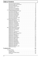
... Removing the LCD Bezel 85 Removing the Camera Module 86 Removing the Inverter Board 87 Removing the LCD/LED Panel 89 Removing the LCD Brackets 90 Removing the LVDS cable 91 Removing the Microphone Cable 92 Removing...the LVDS Cable 100 Replacing the LCD Brackets 101 Replacing the LCD/LED Panel 102 Removing the Inverter Board 103 Replacing the Camera Module 105 Replacing the LCD Bezel 106 Main...Board 122 Replacing the Speaker Module 123 Replacing the Upper Cover 124 Replacing the RTC Battery 128 Replacing the HDD Module 129 Replacing the WLAN Module 131 Replacing the DIMM Modules...
... Removing the LCD Bezel 85 Removing the Camera Module 86 Removing the Inverter Board 87 Removing the LCD/LED Panel 89 Removing the LCD Brackets 90 Removing the LVDS cable 91 Removing the Microphone Cable 92 Removing...the LVDS Cable 100 Replacing the LCD Brackets 101 Replacing the LCD/LED Panel 102 Removing the Inverter Board 103 Replacing the Camera Module 105 Replacing the LCD Bezel 106 Main...Board 122 Replacing the Speaker Module 123 Replacing the Upper Cover 124 Replacing the RTC Battery 128 Replacing the HDD Module 129 Replacing the WLAN Module 131 Replacing the DIMM Modules...
Service Guide
Page 152
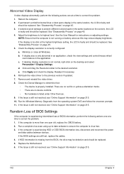
... that the computer is not running on the screen), the LCD is present (different colored spots in the same locations on battery alone as this may be defective and should be replaced. If the display is faulty and should be replaced. Check the ...Windows. d. Readjust if necessary. 6. b. Click and drag the Resolution slider to correct the problem. 1. Remove and reinstall the video driver. 8. There are no device conflicts. • No hardware is experiencing HDD or ODD BIOS information loss, disconnect and reconnect the power and data cables between devices. If the...
... that the computer is not running on the screen), the LCD is present (different colored spots in the same locations on battery alone as this may be defective and should be replaced. If the display is faulty and should be replaced. Check the ...Windows. d. Readjust if necessary. 6. b. Click and drag the Resolution slider to correct the problem. 1. Remove and reinstall the video driver. 8. There are no device conflicts. • No hardware is experiencing HDD or ODD BIOS information loss, disconnect and reconnect the power and data cables between devices. If the...
Service Guide
Page 171
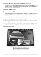
... Jumper Item JP9 Description Clear CMOS Jumper Chapter 3 161 Power Off the system, and remove HDD, AC and Battery from the HW Gap. 5. Press Power Button until BIOS POST is cleared. If there is no Password request, BIOS Password is finished, then remove the tool from the machine. 2. NOTE: These steps are only for enabling...
... Jumper Item JP9 Description Clear CMOS Jumper Chapter 3 161 Power Off the system, and remove HDD, AC and Battery from the HW Gap. 5. Press Power Button until BIOS POST is cleared. If there is no Password request, BIOS Password is finished, then remove the tool from the machine. 2. NOTE: These steps are only for enabling...
Service Guide
Page 227
...Battery Replacing 138 Battery Pack Removing 47 BIOS Utility 27-35 Advanced 30 Boot 33 Exit 34 Navigating 27 Onboard Device Configuration 31 Power 33 Save and Exit 34 Security 30 System Security 34 Bluetooth Module (Discrete) Removing 72 Board Layout Top View 157 brightness hotkeys 13 C Camera Module Removing... 150 External Module Disassembly Flowchart 46 F Features 1 Front View 6 FRU (Field Replaceable Unit) List 163 H Hard Disk Drive Removing 57 Replacing 129 HDTV Switch Failure 151 Hibernation mode hotkey 13 Hot Keys 11 I Indicators 9 Intermittent Problems 152 Internal Microphone Failure ...
...Battery Replacing 138 Battery Pack Removing 47 BIOS Utility 27-35 Advanced 30 Boot 33 Exit 34 Navigating 27 Onboard Device Configuration 31 Power 33 Save and Exit 34 Security 30 System Security 34 Bluetooth Module (Discrete) Removing 72 Board Layout Top View 157 brightness hotkeys 13 C Camera Module Removing... 150 External Module Disassembly Flowchart 46 F Features 1 Front View 6 FRU (Field Replaceable Unit) List 163 H Hard Disk Drive Removing 57 Replacing 129 HDTV Switch Failure 151 Hibernation mode hotkey 13 Hot Keys 11 I Indicators 9 Intermittent Problems 152 Internal Microphone Failure ...


