Quick Start Guide
Page 7
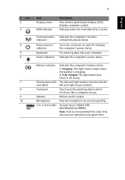
... Fully charged: The light shows blue when in -1 card reader Indicates the computer's battery status. 1. Delivers audio output. Charging: The light shows amber when the battery is active. Internal microphone for sound recording. Communication indicator Power button / indicator Keyboard Power... indicator Indicates the computer's wireless connectivity device status. For entering data into your computer. Battery indicator Click buttons (left and right mouse buttons. The left and right buttons function like a computer mouse. Indicates the ...
... Fully charged: The light shows blue when in -1 card reader Indicates the computer's battery status. 1. Delivers audio output. Charging: The light shows amber when the battery is active. Internal microphone for sound recording. Communication indicator Power button / indicator Keyboard Power... indicator Indicates the computer's wireless connectivity device status. For entering data into your computer. Battery indicator Click buttons (left and right mouse buttons. The left and right buttons function like a computer mouse. Indicates the ...
Quick Start Guide
Page 9
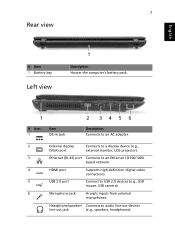
... Left view 1 Description Houses the computer's battery pack. 1 # Icon 1 Item DC-in jack 2 34 56 Description Connects to an AC adapter. 2 External display Connects to a display device (e.g., (VGA) port external monitor, LCD ...
... Left view 1 Description Houses the computer's battery pack. 1 # Icon 1 Item DC-in jack 2 34 56 Description Connects to an AC adapter. 2 External display Connects to a display device (e.g., (VGA) port external monitor, LCD ...
Quick Start Guide
Page 11
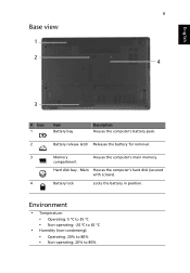
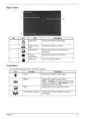
Environment • Temperature: • Operating: 5 °C to 35 °C • Non-operating: -20 °C to 65 °C • Humidity (non-condensing): • Operating: 20% to 80% • Non-operating: 20% to 80% English 9 Base view 1 2 4 3 # Icon 1 Item Battery bay Description Houses the computer's battery pack. 2 Battery release latch Releases the battery for removal. 3 Memory Houses the computer's main memory. Main Houses the computer's hard disk (secured with screws). 4 Battery lock Locks the battery in position. compartment Hard disk bay -
Environment • Temperature: • Operating: 5 °C to 35 °C • Non-operating: -20 °C to 65 °C • Humidity (non-condensing): • Operating: 20% to 80% • Non-operating: 20% to 80% English 9 Base view 1 2 4 3 # Icon 1 Item Battery bay Description Houses the computer's battery pack. 2 Battery release latch Releases the battery for removal. 3 Memory Houses the computer's main memory. Main Houses the computer's hard disk (secured with screws). 4 Battery lock Locks the battery in position. compartment Hard disk bay -
Service Guide
Page 7
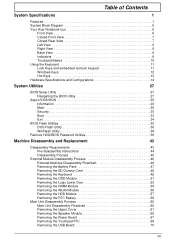
Table of Contents System Specifications 1 Features 1 System Block Diagram 5 Your Acer Notebook tour 6 Front View 6 Closed Front View 7 Closed Rear View 7 ...Specifications and Configurations 14 System Utilities 27 BIOS Setup Utility 27 Navigating the BIOS Utility 27 Aspire 5336 BIOS 28 Information 28 Main 29 Security 30 Boot 33 Exit 34 BIOS Flash Utilities 35...44 Disassembly Process 45 External Module Disassembly Process 46 External Modules Disassembly Flowchart 46 Removing the Battery Pack 47 Removing the SD Dummy Card 48 Removing the Keyboard 49 Removing the ODD Module...
Table of Contents System Specifications 1 Features 1 System Block Diagram 5 Your Acer Notebook tour 6 Front View 6 Closed Front View 7 Closed Rear View 7 ...Specifications and Configurations 14 System Utilities 27 BIOS Setup Utility 27 Navigating the BIOS Utility 27 Aspire 5336 BIOS 28 Information 28 Main 29 Security 30 Boot 33 Exit 34 BIOS Flash Utilities 35...44 Disassembly Process 45 External Module Disassembly Process 46 External Modules Disassembly Flowchart 46 Removing the Battery Pack 47 Removing the SD Dummy Card 48 Removing the Keyboard 49 Removing the ODD Module...
Service Guide
Page 8
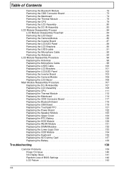
...119 Replacing the Touchpad FFC 121 Replacing the Power Board 122 Replacing the Speaker Module 123 Replacing the Upper Cover 124 Replacing the RTC Battery 128 Replacing the HDD Module 129 Replacing the WLAN Module 131 Replacing the DIMM Modules 132 Replacing the Lower Logic Door 133 Replacing the... ODD Module 134 Replacing the Keyboard 136 Replacing the SD Dummy Card 137 Replacing the Battery 138 Troubleshooting 139 Common Problems 139 Power On Issue 140 No Display Issue 141 Random Loss of BIOS Settings 142 LCD Failure 143 ...
...119 Replacing the Touchpad FFC 121 Replacing the Power Board 122 Replacing the Speaker Module 123 Replacing the Upper Cover 124 Replacing the RTC Battery 128 Replacing the HDD Module 129 Replacing the WLAN Module 131 Replacing the DIMM Modules 132 Replacing the Lower Logic Door 133 Replacing the... ODD Module 134 Replacing the Keyboard 136 Replacing the SD Dummy Card 137 Replacing the Battery 138 Troubleshooting 139 Common Problems 139 Power On Issue 140 No Display Issue 141 Random Loss of BIOS Settings 142 LCD Failure 143 ...
Service Guide
Page 12
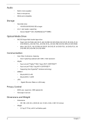
...-R DL, 4X DVD+R DL, 6X DVD-RW, 8X DVD+RW, 5X DVD-RAM Communication • Acer Video Conference, featuring: • Acer Crystal Eye webcam with 1280 x 1024 resolution • WLAN: • Acer InviLink™ Nplify™ 802.11b/g/n Wi-Fi CERTIFIED™ • Acer InviLink™ 802.11b/g Wi-Fi CERTIFIED™ • Supporting... Dimensions and Weight • Dimensions • 381 (W) x 253 (D) x 25/34 (H) mm (14.99 x 9.96 x 0.98/1.33 inches) • Weight • 2.6 kg (5.74 lbs.) with 6-cell battery pack 2 Chapter 1
...-R DL, 4X DVD+R DL, 6X DVD-RW, 8X DVD+RW, 5X DVD-RAM Communication • Acer Video Conference, featuring: • Acer Crystal Eye webcam with 1280 x 1024 resolution • WLAN: • Acer InviLink™ Nplify™ 802.11b/g/n Wi-Fi CERTIFIED™ • Acer InviLink™ 802.11b/g Wi-Fi CERTIFIED™ • Supporting... Dimensions and Weight • Dimensions • 381 (W) x 253 (D) x 25/34 (H) mm (14.99 x 9.96 x 0.98/1.33 inches) • Weight • 2.6 kg (5.74 lbs.) with 6-cell battery pack 2 Chapter 1
Service Guide
Page 13
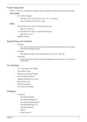
...6-cell Li-ion standard battery pack • Battery life: 3.5 hours • 41.4 Wh 2800 mAh 4-cell Li-ion standard battery pack • Battery life: 3 hours • ENERGY STAR® Special Keys and Controls • Keyboard • 103-/104-/107-key Acer FineTip keyboard with independent ...Microphone-in jack • Ethernet (RJ-45) port • DC-in jack for AC adapter Software • Productivity • Acer Backup Manager • Acer ePower Management • Acer eRecovery Management • Adobe® Flash® Player 10.1 • Adobe® Reader® 9.1 • eSobi™...
...6-cell Li-ion standard battery pack • Battery life: 3.5 hours • 41.4 Wh 2800 mAh 4-cell Li-ion standard battery pack • Battery life: 3 hours • ENERGY STAR® Special Keys and Controls • Keyboard • 103-/104-/107-key Acer FineTip keyboard with independent ...Microphone-in jack • Ethernet (RJ-45) port • DC-in jack for AC adapter Software • Productivity • Acer Backup Manager • Acer ePower Management • Acer eRecovery Management • Adobe® Flash® Player 10.1 • Adobe® Reader® 9.1 • eSobi™...
Service Guide
Page 14
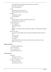
...Acer Identity Card • Acer Registration • Acer Updater • eBay® shortcut 2009 (Canada, France, Germany, Italy, Mexico, Spain, UK, US only) • Netflix shortcut (US only) Optional Items • 1 / 2 GB DDR3 soDIMM module • 3-pin 65 W AC adapter • 6-cell Li-ion battery... Oberon GameZone (except US, Canada, Hong Kong, Korea) • WildTangent®1 (US, Canada only) • Communication and ISP • Acer Crystal Eye • Microsoft® Silverlight™ • Skype™ • Windows Live™ Essentials - • Microsoft® Office 2010...
...Acer Identity Card • Acer Registration • Acer Updater • eBay® shortcut 2009 (Canada, France, Germany, Italy, Mexico, Spain, UK, US only) • Netflix shortcut (US only) Optional Items • 1 / 2 GB DDR3 soDIMM module • 3-pin 65 W AC adapter • 6-cell Li-ion battery... Oberon GameZone (except US, Canada, Hong Kong, Korea) • WildTangent®1 (US, Canada only) • Communication and ISP • Acer Crystal Eye • Microsoft® Silverlight™ • Skype™ • Windows Live™ Essentials - • Microsoft® Office 2010...
Service Guide
Page 16
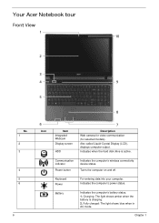
...Acer Notebook tour Front View 1 10 2 3 4 9 5 No. 1 2 3 4 5 6 6 8 6 Icon Item Integrated Webcam Display screen HDD 7 Description Web camera for video communication (for selected models). Fully charged: The light shows blue when in AC mode. Indicates the computer's power status. Keyboard Power Battery... For entering data into your computer. Indicates when the hard disk drive is charging. 2. Turns the computer on and off. Indicates the computer's battery status. 1. Communication indicator Power button Indicates...
...Acer Notebook tour Front View 1 10 2 3 4 9 5 No. 1 2 3 4 5 6 6 8 6 Icon Item Integrated Webcam Display screen HDD 7 Description Web camera for video communication (for selected models). Fully charged: The light shows blue when in AC mode. Indicates the computer's power status. Keyboard Power Battery... For entering data into your computer. Indicates when the hard disk drive is charging. 2. Turns the computer on and off. Indicates the computer's battery status. 1. Communication indicator Power button Indicates...

Service Guide
Page 17
...: Push to remove/install the card. NOTE: The front panel indicators are visible even when the computer cover is closed. No. 1 Icon Item Battery bay 1 Description Houses the computer's battery pack. Closed Front View No. 1 1 Icon Item 2-in-1 card reader Closed Rear View Description Accepts Secure Digital (SD), MultiMediaCard (MMC). Chapter 1 7 Touch...
...: Push to remove/install the card. NOTE: The front panel indicators are visible even when the computer cover is closed. No. 1 Icon Item Battery bay 1 Description Houses the computer's battery pack. Closed Front View No. 1 1 Icon Item 2-in-1 card reader Closed Rear View Description Accepts Secure Digital (SD), MultiMediaCard (MMC). Chapter 1 7 Touch...
Service Guide
Page 19
... green when in position. Indicates when the hard disk drive is charging. 2. Battery HDD Indicates the computer's battery status. Base View 1 2 4 No. 1 2 3 4 3 Icon Item Battery bay Description Houses the computer's battery pack. Battery release latch Hard disk bay Memory compartment Battery lock Releases the battery for removal. Indicators The computer has several easy-to-read status indicators...
... green when in position. Indicates when the hard disk drive is charging. 2. Battery HDD Indicates the computer's battery status. Base View 1 2 4 No. 1 2 3 4 3 Icon Item Battery bay Description Houses the computer's battery pack. Battery release latch Hard disk bay Memory compartment Battery lock Releases the battery for removal. Indicators The computer has several easy-to-read status indicators...
Service Guide
Page 32
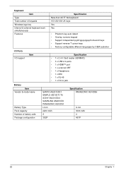
Keyboard Item Type Total number of keypads Windows logo key Internal & external keyboard work simultaneously Features Specification New Acer AC7T flat keyboard 103-US/104-UK keys Yes Yes • Phantom key auto detect • Overlay ... x HDMI™ port • 1 x external CRT • 1 x Headphone • 1 x MIC • 1 x RJ-45 • 1 x DC-in jack Battery Item Vendor & model name Battery Type Pack capacity Number of battery cells Package configuration SANYO AS2010D31 SIMPLO AS10D71/75 SONY AS2010D41 SAMSUNG AS2010D6 PANASONIC AS10D51 Li-ion 2200 mAh 6 3S2P Specification PANASONIC...
Keyboard Item Type Total number of keypads Windows logo key Internal & external keyboard work simultaneously Features Specification New Acer AC7T flat keyboard 103-US/104-UK keys Yes Yes • Phantom key auto detect • Overlay ... x HDMI™ port • 1 x external CRT • 1 x Headphone • 1 x MIC • 1 x RJ-45 • 1 x DC-in jack Battery Item Vendor & model name Battery Type Pack capacity Number of battery cells Package configuration SANYO AS2010D31 SIMPLO AS10D71/75 SONY AS2010D41 SAMSUNG AS2010D6 PANASONIC AS10D51 Li-ion 2200 mAh 6 3S2P Specification PANASONIC...

Service Guide
Page 35
... such as the CPU and hard disk may be power managed in low power state Discharging • Amber and blinking - Battery full • Amber blinking - Battery in the system are turned off completely. The system saves all system states and data onto disk prior to 2TB with AC...) Working (G0/S0) S3 Sleeping State On S4 Sleeping State Specification Realtek RTS5137-GR 24 Pin QFN 2-in the system are turned off completely. Battery abnormal stop charge or batter in this state. All devices in -1 card reader, supporting: • Secure Digital™ (SD) Card, MultiMediaCard™...
... such as the CPU and hard disk may be power managed in low power state Discharging • Amber and blinking - Battery full • Amber blinking - Battery in the system are turned off completely. The system saves all system states and data onto disk prior to 2TB with AC...) Working (G0/S0) S3 Sleeping State On S4 Sleeping State Specification Realtek RTS5137-GR 24 Pin QFN 2-in the system are turned off completely. Battery abnormal stop charge or batter in this state. All devices in -1 card reader, supporting: • Secure Digital™ (SD) Card, MultiMediaCard™...
Service Guide
Page 45
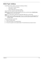
... versions of system programs • New features or options • Restore a BIOS when it becomes corrupted. The flash utility has auto-execution function. If the battery pack does not contain enough power to run the flash utility. Chapter 2 35 BIOS Flash Utilities The BIOS flash memory update is not completely loaded.
... versions of system programs • New features or options • Restore a BIOS when it becomes corrupted. The flash utility has auto-execution function. If the battery pack does not contain enough power to run the flash utility. Chapter 2 35 BIOS Flash Utilities The BIOS flash memory update is not completely loaded.

Service Guide
Page 56
... and signal cables from the mass produced model. External Module Disassembly Process IMPORTANT: The outside housing and color may vary from system Remove Battery Remove SD Dummy Card Remove Lower Logic Door Remove ODD Remove Keyboard Screw List Step ODD Module ODD Bracket Lower Logic Door WLAN Module ...HDD Carrier 46 Remove DIMMs Screw M 2.5*8 M2*3 M2.5*8 M2*3 M3*3 Remove WLAN Remove HDD Remove RTC Battery Quantity 1 2 2 1 4 Part No. 86.R4F02.002 86.R4F02.004 86.R4F02.002 86.R4F02.004 86.R4F02.005 Chapter 3 For example, if ...
... and signal cables from the mass produced model. External Module Disassembly Process IMPORTANT: The outside housing and color may vary from system Remove Battery Remove SD Dummy Card Remove Lower Logic Door Remove ODD Remove Keyboard Screw List Step ODD Module ODD Bracket Lower Logic Door WLAN Module ...HDD Carrier 46 Remove DIMMs Screw M 2.5*8 M2*3 M2.5*8 M2*3 M3*3 Remove WLAN Remove HDD Remove RTC Battery Quantity 1 2 2 1 4 Part No. 86.R4F02.002 86.R4F02.004 86.R4F02.002 86.R4F02.004 86.R4F02.005 Chapter 3 For example, if ...
Service Guide
Page 57
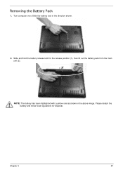
Please detach the battery and follow local regulations for disposal. Chapter 3 47 Slide the battery lock in the above image. Slide and hold the battery release latch to the release position (1), then lift out the battery pack from the main unit (2). 2 1 NOTE: The battery has been highlighted with a yellow oval as shown in the direction shown. 2. Removing the Battery Pack 1. Turn computer over.
Please detach the battery and follow local regulations for disposal. Chapter 3 47 Slide the battery lock in the above image. Slide and hold the battery release latch to the release position (1), then lift out the battery pack from the main unit (2). 2 1 NOTE: The battery has been highlighted with a yellow oval as shown in the direction shown. 2. Removing the Battery Pack 1. Turn computer over.

Service Guide
Page 61
Pull the ODD module out from the chassis. Screw Type Chapter 3 51 See "Removing the Battery Pack" on page 47. 2. Step ODD Module Size M2.5*8 Quantity 1 3. Remove the one (1) screw securing the ODD module. Removing the ODD Module 1.
Pull the ODD module out from the chassis. Screw Type Chapter 3 51 See "Removing the Battery Pack" on page 47. 2. Step ODD Module Size M2.5*8 Quantity 1 3. Remove the one (1) screw securing the ODD module. Removing the ODD Module 1.

Service Guide
Page 69
Using plastic tweezers, lift the RTC battery from mainboard connector. Removing the RTC Battery 1. See "Removing the WLAN Module" on page 55. 2. Chapter 3 59
Using plastic tweezers, lift the RTC battery from mainboard connector. Removing the RTC Battery 1. See "Removing the WLAN Module" on page 55. 2. Chapter 3 59

Service Guide
Page 71
See "External Module Disassembly Process" on the lower cover and four (4) screws from the battery bay. Removing the Upper Cover 1. Turn the computer over. Step Lower Cover Size M2.5*8 (red callout) M2*3 (green callout) Quantity 10 4 Screw Type Chapter 3 61 Remove the ten (10) screws on page 46. 2.
See "External Module Disassembly Process" on the lower cover and four (4) screws from the battery bay. Removing the Upper Cover 1. Turn the computer over. Step Lower Cover Size M2.5*8 (red callout) M2*3 (green callout) Quantity 10 4 Screw Type Chapter 3 61 Remove the ten (10) screws on page 46. 2.

Service Guide
Page 137
6. Replace the ten (10) screws on the lower cover and four (4) screws in the battery bay. Step Upper Cover Size M2.5*5 Quantity 8 Screw Type 7. Step Lower Cover Size M2.5*8 (red callout) M2*3 (green callout) Quantity 10 4 Screw Type Chapter 3 127 Turn the computer over. Replace the eight (8) screws to secure the upper cover as shown.
6. Replace the ten (10) screws on the lower cover and four (4) screws in the battery bay. Step Upper Cover Size M2.5*5 Quantity 8 Screw Type 7. Step Lower Cover Size M2.5*8 (red callout) M2*3 (green callout) Quantity 10 4 Screw Type Chapter 3 127 Turn the computer over. Replace the eight (8) screws to secure the upper cover as shown.


