Quick Start Guide
Page 7
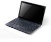
... Power button / indicator Keyboard Power indicator Indicates the computer's wireless connectivity device status. Battery indicator Click buttons (left and right mouse buttons. Note: Push to remove/install the card. Delivers audio output. 5 English # Icon 2 3 4 5 6 7 8 9 10 Item Display screen HDD indicator Description Also called Liquid-Crystal Display...
... Power button / indicator Keyboard Power indicator Indicates the computer's wireless connectivity device status. Battery indicator Click buttons (left and right mouse buttons. Note: Push to remove/install the card. Delivers audio output. 5 English # Icon 2 3 4 5 6 7 8 9 10 Item Display screen HDD indicator Description Also called Liquid-Crystal Display...
Service Guide
Page 8
... Connector Board 73 Removing the Mainboard 74 Removing the Thermal Module 78 Removing the CPU 79 Removing the LCD Assembly 80 Removing the DC-IN Assembly 83 LCD Module Disassembly Process 84 LCD Module Disassembly Flowchart 84 Removing the LCD Bezel 85 Removing the Camera Module 86 Removing the Inverter Board 87 Removing the LCD/LED Panel 89 Removing the LCD Brackets 90 Removing the LVDS cable...
... Connector Board 73 Removing the Mainboard 74 Removing the Thermal Module 78 Removing the CPU 79 Removing the LCD Assembly 80 Removing the DC-IN Assembly 83 LCD Module Disassembly Process 84 LCD Module Disassembly Flowchart 84 Removing the LCD Bezel 85 Removing the Camera Module 86 Removing the Inverter Board 87 Removing the LCD/LED Panel 89 Removing the LCD Brackets 90 Removing the LVDS cable...
Service Guide
Page 55
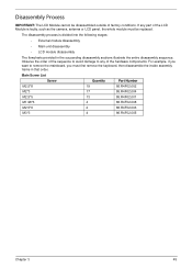
The disassembly process is faulty, such as the camera, antenna or LCD panel, the whole module must first remove the keyboard, then disassemble the inside assembly frame in the succeeding disassembly sections illustrate the entire disassembly sequence. Main Screw List ...want to any part of the hardware components. Observe the order of the sequence to avoid damage to remove the mainboard, you must be disassembled outside of factory conditions. If any of the LCD Module is divided into the following stages: • External module disassembly • Main unit disassembly &#...
The disassembly process is faulty, such as the camera, antenna or LCD panel, the whole module must first remove the keyboard, then disassemble the inside assembly frame in the succeeding disassembly sections illustrate the entire disassembly sequence. Main Screw List ...want to any part of the hardware components. Observe the order of the sequence to avoid damage to remove the mainboard, you must be disassembled outside of factory conditions. If any of the LCD Module is divided into the following stages: • External module disassembly • Main unit disassembly &#...
Service Guide
Page 70
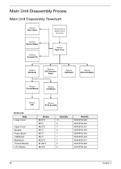
... Main Unit Disassembly Flowchart Remove Power Board Remove External Modules before proceeding Remove Speaker Module Remove Touchpad FFC Remove Upper Cover Remove Mainboard Remove ODD Connector Board Remove USB Board Remove Bluetooth Module Remove Thermal Module Remove LCD Module Remove CPU Remove DC-IN Assembly Screw List Step Lower Cover Upper Cover Speaker Power Board USB Board Mainboard Thermal Module LCD Module Screw M2.5*8 M2...
... Main Unit Disassembly Flowchart Remove Power Board Remove External Modules before proceeding Remove Speaker Module Remove Touchpad FFC Remove Upper Cover Remove Mainboard Remove ODD Connector Board Remove USB Board Remove Bluetooth Module Remove Thermal Module Remove LCD Module Remove CPU Remove DC-IN Assembly Screw List Step Lower Cover Upper Cover Speaker Power Board USB Board Mainboard Thermal Module LCD Module Screw M2.5*8 M2...
Service Guide
Page 85
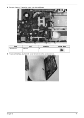
To prevent damage, lay the LCD panel flat and cover the panel as shown. Remove the one (1) securing screw from the mainboard. Chapter 3 75 Step Mainboard Size M2.5*5 Quantity 1 Screw Type 6. 5.
To prevent damage, lay the LCD panel flat and cover the panel as shown. Remove the one (1) securing screw from the mainboard. Chapter 3 75 Step Mainboard Size M2.5*5 Quantity 1 Screw Type 6. 5.
Service Guide
Page 86
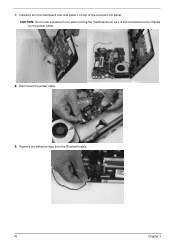
CAUTION: Do not use excessive force when turning the mainboard over and place it is still connected to the chassis by the power cable. 8. Carefully turn the mainboard over as it on top of the covered LCD panel. 7. Remove the adhesive tape from the Bluetooth cable. 76 Chapter 3 Disconnect the power cable. 9.
CAUTION: Do not use excessive force when turning the mainboard over and place it is still connected to the chassis by the power cable. 8. Carefully turn the mainboard over as it on top of the covered LCD panel. 7. Remove the adhesive tape from the Bluetooth cable. 76 Chapter 3 Disconnect the power cable. 9.
Service Guide
Page 90
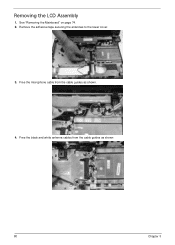
Remove the adhesive tape securing the antennas to the lower cover. 3. Free the black and white antenna cables from the cable guides as shown . 80 Chapter 3 Free the microphone cable from the cable guides as shown. 4. See "Removing the Mainboard" on page 74. 2. Removing the LCD Assembly 1.
Remove the adhesive tape securing the antennas to the lower cover. 3. Free the black and white antenna cables from the cable guides as shown . 80 Chapter 3 Free the microphone cable from the cable guides as shown. 4. See "Removing the Mainboard" on page 74. 2. Removing the LCD Assembly 1.
Service Guide
Page 91
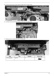
Continue removing the black antenna cable from the LCD assembly. Remove four (4) screws from the cable guides. 7. Step LCD Assembly Size M2.5*8 Quantity 4 Screw Type Chapter 3 81 5. Continue removing the white antenna cable from the cable guides. 6.
Continue removing the black antenna cable from the LCD assembly. Remove four (4) screws from the cable guides. 7. Step LCD Assembly Size M2.5*8 Quantity 4 Screw Type Chapter 3 81 5. Continue removing the white antenna cable from the cable guides. 6.
Service Guide
Page 92
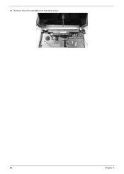
8. Remove the LCD assembly from the lower cover. 82 Chapter 3
8. Remove the LCD assembly from the lower cover. 82 Chapter 3
Service Guide
Page 93
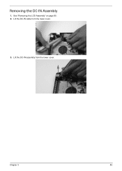
Lift the DC-IN cable from the lower cover. Chapter 3 83 Lift the DC-IN assembly from the lower cover. 3. See "Removing the LCD Assembly" on page 80. 2. Removing the DC-IN Assembly 1.
Lift the DC-IN cable from the lower cover. Chapter 3 83 Lift the DC-IN assembly from the lower cover. 3. See "Removing the LCD Assembly" on page 80. 2. Removing the DC-IN Assembly 1.
Service Guide
Page 94
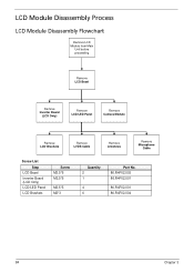
LCD Module Disassembly Process LCD Module Disassembly Flowchart Remove LCD Module from Main Unit before proceeding Remove LCD Bezel Remove Inverter Board (LCD Only) Remove LCD/LED Panel Remove Camera Module Remove LCD Brackets Remove LVDS Cable Remove Antennas Remove Microphone Cable Screw List Step LCD Bezel Inverter Board (LCD Only) LCD/LED Panel LCD Brackets Screw M2.5*6 M2.5*5 M2.5*5 M2*3 Quantity 2 1 4 6 Part No. 86.R4F02.003 86.R4F02.001 86.R4F02.001 86.R4F02.004 84 Chapter 3
LCD Module Disassembly Process LCD Module Disassembly Flowchart Remove LCD Module from Main Unit before proceeding Remove LCD Bezel Remove Inverter Board (LCD Only) Remove LCD/LED Panel Remove Camera Module Remove LCD Brackets Remove LVDS Cable Remove Antennas Remove Microphone Cable Screw List Step LCD Bezel Inverter Board (LCD Only) LCD/LED Panel LCD Brackets Screw M2.5*6 M2.5*5 M2.5*5 M2*3 Quantity 2 1 4 6 Part No. 86.R4F02.003 86.R4F02.001 86.R4F02.001 86.R4F02.004 84 Chapter 3
Service Guide
Page 95
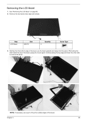
NOTE: If necessary, use a pry to remove the bezel. Chapter 3 85 Starting from the panel. Removing the LCD Bezel 1. Step LCD Bezel Size M2.5*6 Quantity 2 Screw Type 3. Remove the two bezel screw caps and screws. Continue along the side toward the top of the bezel, prying the covers apart. See "Removing the LCD Bezel" on page 85. 2. Work along the top edge and down the other side to lift up the outside edges of the bezel, pry the bezel upwards and away from the bottom edge of the bezel.
NOTE: If necessary, use a pry to remove the bezel. Chapter 3 85 Starting from the panel. Removing the LCD Bezel 1. Step LCD Bezel Size M2.5*6 Quantity 2 Screw Type 3. Remove the two bezel screw caps and screws. Continue along the side toward the top of the bezel, prying the covers apart. See "Removing the LCD Bezel" on page 85. 2. Work along the top edge and down the other side to lift up the outside edges of the bezel, pry the bezel upwards and away from the bottom edge of the bezel.
Service Guide
Page 96
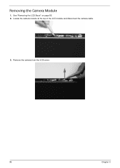
See "Removing the LCD Bezel" on page 85. 2. Remove the camera from the LCD cover. 86 Chapter 3 Removing the Camera Module 1. Locate the camera module at the top of the LCD module and disconnect the camera cable. 3.
See "Removing the LCD Bezel" on page 85. 2. Remove the camera from the LCD cover. 86 Chapter 3 Removing the Camera Module 1. Locate the camera module at the top of the LCD module and disconnect the camera cable. 3.
Service Guide
Page 97
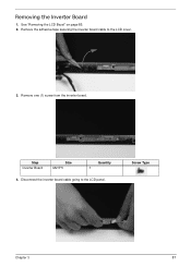
Screw Type Chapter 3 87 Remove one (1) screw from the inverter board. Remove the adhesive tape securing the inverter board cable to the LCD panel. Step Inverter Board Size M2.5*5 Quantity 1 4. Disconnect the inverter board cable going to the LCD cover. 3. Removing the Inverter Board 1. See "Removing the LCD Bezel" on page 85. 2.
Screw Type Chapter 3 87 Remove one (1) screw from the inverter board. Remove the adhesive tape securing the inverter board cable to the LCD panel. Step Inverter Board Size M2.5*5 Quantity 1 4. Disconnect the inverter board cable going to the LCD cover. 3. Removing the Inverter Board 1. See "Removing the LCD Bezel" on page 85. 2.
Service Guide
Page 99
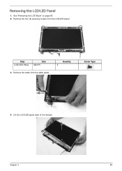
See "Removing the LCD Bezel" on page 85. 2. Remove the cable from the LCD/LED panel. Quantity 4 Screw Type 4. Chapter 3 89 Removing the LCD/LED Panel 1. Lift the LCD/LED panel clear of the module. Step LCD/LED Panel Size M2.5*5 3. Remove the four (4) securing screws from the cable guide.
See "Removing the LCD Bezel" on page 85. 2. Remove the cable from the LCD/LED panel. Quantity 4 Screw Type 4. Chapter 3 89 Removing the LCD/LED Panel 1. Lift the LCD/LED panel clear of the module. Step LCD/LED Panel Size M2.5*5 3. Remove the four (4) securing screws from the cable guide.
Service Guide
Page 100
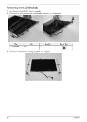
Remove the six (6) securing screws (three on page 89. 2. Screw Type 90 Chapter 3 Remove the LCD brackets by pulling away from the LCD brackets. Step LCD Brackets Size M2*3 Quantity 6 3. Removing the LCD Brackets 1. See "Removing the LCD/LED Panel" on each side) from the LCD panel.
Remove the six (6) securing screws (three on page 89. 2. Screw Type 90 Chapter 3 Remove the LCD brackets by pulling away from the LCD brackets. Step LCD Brackets Size M2*3 Quantity 6 3. Removing the LCD Brackets 1. See "Removing the LCD/LED Panel" on each side) from the LCD panel.

Service Guide
Page 101
LCD LED 3. LCD LED Chapter 3 91 Peel back the mylar securing the LVDS cable. LCD LED 4. See "Removing the LCD/LED Panel" on page 89. 2. Disconnect the LVDS cable and remove it from the back of the panel. Removing the LVDS cable 1. Remove the LVDS cable from the panel.
LCD LED 3. LCD LED Chapter 3 91 Peel back the mylar securing the LVDS cable. LCD LED 4. See "Removing the LCD/LED Panel" on page 89. 2. Disconnect the LVDS cable and remove it from the back of the panel. Removing the LVDS cable 1. Remove the LVDS cable from the panel.
Service Guide
Page 102
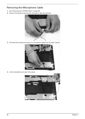
See "Removing the LCD/LED Panel" on page 89. 2. Lift the microphone set clear of the panel. 92 Chapter 3 Removing the Microphone Cable 1. Remove the adhesive securing the microphone cable and antenna. 3. Peel back the foil tabs and remove the microphone cable from the cable channel. 4.
See "Removing the LCD/LED Panel" on page 89. 2. Lift the microphone set clear of the panel. 92 Chapter 3 Removing the Microphone Cable 1. Remove the adhesive securing the microphone cable and antenna. 3. Peel back the foil tabs and remove the microphone cable from the cable channel. 4.
Service Guide
Page 104
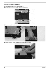
Removing the Antennas 1. Using a flat plastic tool, pry the antenna assembly clear of the device. 94 Chapter 3 See "Removing the LCD/LED Panel" on page 89. 2. Peel back the foil tabs securing the antenna to the LCD cover. 3. Remove the cable from the cable guides. 4.
Removing the Antennas 1. Using a flat plastic tool, pry the antenna assembly clear of the device. 94 Chapter 3 See "Removing the LCD/LED Panel" on page 89. 2. Peel back the foil tabs securing the antenna to the LCD cover. 3. Remove the cable from the cable guides. 4.
Service Guide
Page 105
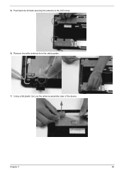
Chapter 3 95 Remove the white antenna from the cable guides. 7. Using a flat plastic tool, pry the antenna assembly clear of the device. 5. Peel back the foil tabs securing the antenna to the LCD cover. 6.
Chapter 3 95 Remove the white antenna from the cable guides. 7. Using a flat plastic tool, pry the antenna assembly clear of the device. 5. Peel back the foil tabs securing the antenna to the LCD cover. 6.


