
User Manual
Page 2
... centers. TABLE OF CONTENTS LIMITED WARRANTY 2 IMPORTANT PRECAUTIONS 3 BEFORE YOU BEGIN 4 ASSEMBLY 5 ADJUSTMENT 16 TROUBLE-SHOOTING AND MAINTENANCE 18 CABLE DIAGRAM 19 ORDERING REPLACEMENT PARTS Back Cover Note: An EXPLODED DRAWING/PART LIST and a PART IDENTIFICATION CHART are attached to the center of... to you specific legal rights. Some states do not allow the exclusion or limitation of ICON Health & Fitness, Inc. WEIDER is authorized by sufficient proof of its authorized service centers with respect to the original purchaser. No other transportation charges prepaid, accompanied...
... centers. TABLE OF CONTENTS LIMITED WARRANTY 2 IMPORTANT PRECAUTIONS 3 BEFORE YOU BEGIN 4 ASSEMBLY 5 ADJUSTMENT 16 TROUBLE-SHOOTING AND MAINTENANCE 18 CABLE DIAGRAM 19 ORDERING REPLACEMENT PARTS Back Cover Note: An EXPLODED DRAWING/PART LIST and a PART IDENTIFICATION CHART are attached to the center of... to you specific legal rights. Some states do not allow the exclusion or limitation of ICON Health & Fitness, Inc. WEIDER is authorized by sufficient proof of its authorized service centers with respect to the original purchaser. No other transportation charges prepaid, accompanied...
User Manual
Page 3
..., butterfly arms, leg lever, lat bar, or nylon strap while weights are adequately informed of the home gym system are raised. Make sure that the cables remain on a level surface. This is designed to tip. 11. Use the home gym system only on the pulleys at a time. 8. Always wear...by or through the use the lat bar. Always stand on all instructions in this or any exercise program, consult your physician. If the cables bind while you feel pain or dizziness at all parts often. Read all of serious injury, read the following important precautions before using the ...
..., butterfly arms, leg lever, lat bar, or nylon strap while weights are adequately informed of the home gym system are raised. Make sure that the cables remain on a level surface. This is designed to tip. 11. Use the home gym system only on the pulleys at a time. 8. Always wear...by or through the use the lat bar. Always stand on all instructions in this or any exercise program, consult your physician. If the cables bind while you feel pain or dizziness at all parts often. Read all of serious injury, read the following important precautions before using the ...
User Manual
Page 5
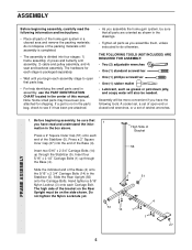
... the end of this manual. Assembly will also be needed. Press a 2" Square Inner Cap (27) into four stages: 1) frame assembly, 2) press and butterfly arm assembly, 3) cable and pulley assembly, and 4) seat and backrest assembly. Before beginning assembly, be sure that you have read the following tools: A socket set, a set of open...
... the end of this manual. Assembly will also be needed. Press a 2" Square Inner Cap (27) into four stages: 1) frame assembly, 2) press and butterfly arm assembly, 3) cable and pulley assembly, and 4) seat and backrest assembly. Before beginning assembly, be sure that you have read the following tools: A socket set, a set of open...
User Manual
Page 8
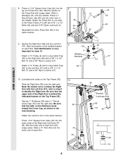
... the upper end of the welded bracket on the Retainers bend toward the Cover Cap, as shown in the inset drawing. Attach a "V"-Pulley (6) and a Long Cable Trap (50) to the Right Arm (48) with a 3/8" x 2 1/2" Bolt (7) and a 3/8" Nylon Locknut (21). 8 31 44 49 46 22 9 50 6 Welded Brackets ... 49 46 47 ARM ASSEMBLY 10. Press a 1" Round Inner Cap (49) into the other Press Arm (46) in the same manner. Attach a "V"-Pulley (6) and a Long Cable Trap (50) to the Left Arm (47) with a 3/8" x 2 1/2" Bolt (7) and a 3/8" Nylon Locknut (21). Tap two 1" Retainers (69) and a 1" Round Cover...
... the upper end of the welded bracket on the Retainers bend toward the Cover Cap, as shown in the inset drawing. Attach a "V"-Pulley (6) and a Long Cable Trap (50) to the Right Arm (48) with a 3/8" x 2 1/2" Bolt (7) and a 3/8" Nylon Locknut (21). 8 31 44 49 46 22 9 50 6 Welded Brackets ... 49 46 47 ARM ASSEMBLY 10. Press a 1" Round Inner Cap (49) into the other Press Arm (46) in the same manner. Attach a "V"-Pulley (6) and a Long Cable Trap (50) to the Left Arm (47) with a 3/8" x 2 1/2" Bolt (7) and a 3/8" Nylon Locknut (21). Tap two 1" Retainers (69) and a 1" Round Cover...
User Manual
Page 10
...is on the indicated side of the cables. Be sure that the Cable is between the Pulley and the hook. Route the Long Cable (23) around the "V"- 17 Pulley (6) on page 19 of this section, identify the Long Cable (23) and the Short Cable (58) by comparing the lengths ...of the Pulley and that the Long Cable Trap is positioned to verify proper cable routing. Before beginning this manual to hold the Cable in place. Be sure that the Long Cable Trap (50) is in place. 17. Route the Long Cable around a "V"-Pulley (6). Tighten the 3/8" x 2 1/2" Bolt (7) ...
...is on the indicated side of the cables. Be sure that the Cable is between the Pulley and the hook. Route the Long Cable (23) around the "V"- 17 Pulley (6) on page 19 of this section, identify the Long Cable (23) and the Short Cable (58) by comparing the lengths ...of the Pulley and that the Long Cable Trap is positioned to verify proper cable routing. Before beginning this manual to hold the Cable in place. Be sure that the Long Cable Trap (50) is in place. 17. Route the Long Cable around a "V"-Pulley (6). Tighten the 3/8" x 2 1/2" Bolt (7) ...
User Manual
Page 11
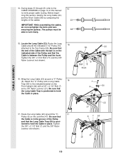
... this 21 step is properly tightened and that the Pulley Bracket (20) can move smoothly. 15 66 12 21 57 21. See the inset drawing. CABLE ASSEMBLY 18. It is turned to the bracket on the Right Arm (48). Tighten the 3/8" x 2" Bolt (12) 55 and the 3/8" Nylon Locknut (21). ... the 5/16" x 5" Bolt (68) is pre-attached. Note: This may come pre-assem- Route the Long Cable (23) around the 3 1/2" Pulley (15) attached to the indicated hole in the groove of the "V"- Route the Long Cable (23) around the "V"- 18 Pulley (6) on the Top Frame (55). Tighten the 3/8" x 2" Bolt (12)...
... this 21 step is properly tightened and that the Pulley Bracket (20) can move smoothly. 15 66 12 21 57 21. See the inset drawing. CABLE ASSEMBLY 18. It is turned to the bracket on the Right Arm (48). Tighten the 3/8" x 2" Bolt (12) 55 and the 3/8" Nylon Locknut (21). ... the 5/16" x 5" Bolt (68) is pre-attached. Note: This may come pre-assem- Route the Long Cable (23) around the 3 1/2" Pulley (15) attached to the indicated hole in the groove of the "V"- Route the Long Cable (23) around the "V"- 18 Pulley (6) on the Top Frame (55). Tighten the 3/8" x 2" Bolt (12)...
User Manual
Page 12
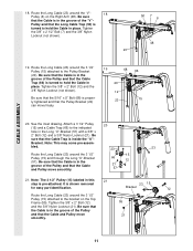
... Bolt (16) and the 3/8" Nylon Locknut (not shown). 23. Wrap the Short Cable (58) around a 3 1/2" Pulley (15). Pulley (6). Be sure that the Cable Trap is turned to hold the Cable in place and that the Cable Trap (66) is routed around the Pulley as shown. 29 16 58 77 Ball...with a 3/8" x 3 1/2" Bolt (16), a 3/8" Flat Washer (9), and a 3/8" Nylon Locknut (21). Locate the Short Cable (58). Wrap the Short Cable (58) around a "V"- Attach the Pulley and a Long 23 Cable Trap (50) inside the bracket on the Leg Lever (29). Note: The 3 1/2" Pulley (15) labeled in place and ...
... Bolt (16) and the 3/8" Nylon Locknut (not shown). 23. Wrap the Short Cable (58) around a 3 1/2" Pulley (15). Pulley (6). Be sure that the Cable Trap is turned to hold the Cable in place and that the Cable Trap (66) is routed around the Pulley as shown. 29 16 58 77 Ball...with a 3/8" x 3 1/2" Bolt (16), a 3/8" Flat Washer (9), and a 3/8" Nylon Locknut (21). Locate the Short Cable (58). Wrap the Short Cable (58) around a "V"- Attach the Pulley and a Long 23 Cable Trap (50) inside the bracket on the Leg Lever (29). Note: The 3 1/2" Pulley (15) labeled in place and ...
User Manual
Page 13
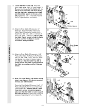
... around the 3 1/2" Pulley (15) attached to the upper hole in the inset drawing. 2 57 10 58 CABLE ASSEMBLY 2 10 57 58 13 It is pre-attached. Be sure that the Cable Trap (66) is routed around the Pulley as shown in the Press Frame (17). Do not completely tighten the... Nylon Locknut. Route the Short Cable (58) around the 3 1/2" Pulley (15) attached to the upper hole in place and that the Cable is turned to the Long "U"-Bracket (57) with a 1/4" Nylon Lock- 28 nut (2) and a 1/4" Flat Washer ...
... around the 3 1/2" Pulley (15) attached to the upper hole in the inset drawing. 2 57 10 58 CABLE ASSEMBLY 2 10 57 58 13 It is pre-attached. Be sure that the Cable Trap (66) is routed around the Pulley as shown in the Press Frame (17). Do not completely tighten the... Nylon Locknut. Route the Short Cable (58) around the 3 1/2" Pulley (15) attached to the upper hole in place and that the Cable is turned to the Long "U"-Bracket (57) with a 1/4" Nylon Lock- 28 nut (2) and a 1/4" Flat Washer ...

User Manual
Page 14
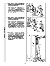
...with a 1/4" Nylon Locknut (2) and a 1/4" Flat Washer (10). Attach the other end of turns, as shown in the inset drawing. Do not com- Attach the Long Cable (23) to the Weight Tube (63) with two 1/4" x 2 1/2" Screws (43) and 30 two 1/4" Flat Washers (10). 23 10 2 67 42 41 43 ...10 SEAT ASSEMBLY 31. CABLE ASSEMBLY 29. Attach the Small "U"-Bracket (67) to the Small "U"- 29 Bracket (67) with a 1/4" Flat Washer (10) onto the Carriage Bolt. Insert the 1/4" x 2 ...
...with a 1/4" Nylon Locknut (2) and a 1/4" Flat Washer (10). Attach the other end of turns, as shown in the inset drawing. Do not com- Attach the Long Cable (23) to the Weight Tube (63) with two 1/4" x 2 1/2" Screws (43) and 30 two 1/4" Flat Washers (10). 23 10 2 67 42 41 43 ...10 SEAT ASSEMBLY 31. CABLE ASSEMBLY 29. Attach the Small "U"-Bracket (67) to the Small "U"- 29 Bracket (67) with a 1/4" Flat Washer (10) onto the Carriage Bolt. Insert the 1/4" x 2 ...

User Manual
Page 15
...80) into the Seat Frame (36). Remove the backing from the 8520 decal and apply it by tightening the cables. The use of the Long Pad Tube (80). See the CABLE DIAGRAM on page 18. 32 44 79 8 3 8 22 ...40 32 78 Slant must be damaged when heavy weight is any slack in the cables, you will be sure that the Press Adjustment Tube is oriented as shown. Align one of the ...80 30 34 29 8520 DECAL PLACEMENT 15 If there is used. Attach the Press Plate (78) to remove it to be explained in ADJUSTMENT, beginning on page 16 of this manual for proper cable routing. Press a...
...80) into the Seat Frame (36). Remove the backing from the 8520 decal and apply it by tightening the cables. The use of the Long Pad Tube (80). See the CABLE DIAGRAM on page 18. 32 44 79 8 3 8 22 ...40 32 78 Slant must be damaged when heavy weight is any slack in the cables, you will be sure that the Press Adjustment Tube is oriented as shown. Align one of the ...80 30 34 29 8520 DECAL PLACEMENT 15 If there is used. Attach the Press Plate (78) to remove it to be explained in ADJUSTMENT, beginning on page 16 of this manual for proper cable routing. Press a...
User Manual
Page 16
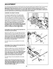
... weight station. 25 26 ATTACHING THE LAT BAR OR NYLON STRAP TO THE HIGH PULLEY STATION Attach the Lat Bar (54) to the Long Cable (23) with a Cable Clip (53). CHANGING THE WEIGHT SETTING To change the weight setting of 12.5 pounds. The Nylon Strap (39) can be performed. Always remove the... 39 58 53 52 54 39 Adjust the length of resistance at each part of the Chain between the Lat Bar and the Pulley Cable with two Cable Clips. The Nylon Strap (39) can be performed. Refer to the exercise poster accompanying this manual to see ADJUSTING AND REMOVING THE LEG PRESS...
... weight station. 25 26 ATTACHING THE LAT BAR OR NYLON STRAP TO THE HIGH PULLEY STATION Attach the Lat Bar (54) to the Long Cable (23) with a Cable Clip (53). CHANGING THE WEIGHT SETTING To change the weight setting of 12.5 pounds. The Nylon Strap (39) can be performed. Always remove the... 39 58 53 52 54 39 Adjust the length of resistance at each part of the Chain between the Lat Bar and the Pulley Cable with two Cable Clips. The Nylon Strap (39) can be performed. Refer to the exercise poster accompanying this manual to see ADJUSTING AND REMOVING THE LEG PRESS...
User Manual
Page 18
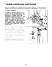
...REPLACEMENT PARTS on the home gym system, can be removed from the Cable Trap (66), Pulley, and "U"-Bracket. TIGHTENING THE CABLES Woven cable, the type of this you use solvents. Remove the cable and re-install it is felt, the cables should be replaced, see drawing 2). Replace any worn parts immediately. ...shown) or remove the 3 1/2" Pulley (15) from the Long "U"-Bracket (57). Re-attach the Pulley and Cable Trap. Slack can stretch slightly when it . 66 57 21 12 If the cables need to the other hole in the Long "U"-Bracket 2 (57). Do not use the home gym system. To...
...REPLACEMENT PARTS on the home gym system, can be removed from the Cable Trap (66), Pulley, and "U"-Bracket. TIGHTENING THE CABLES Woven cable, the type of this you use solvents. Remove the cable and re-install it is felt, the cables should be replaced, see drawing 2). Replace any worn parts immediately. ...shown) or remove the 3 1/2" Pulley (15) from the Long "U"-Bracket (57). Re-attach the Pulley and Cable Trap. Slack can stretch slightly when it . 66 57 21 12 If the cables need to the other hole in the Long "U"-Bracket 2 (57). Do not use the home gym system. To...
User Manual
Page 19
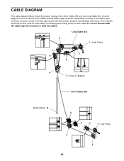
...diagram to be sure that the cable traps do not touch or bind the cables. The starting and ending points of the Short Cable (58) and the Long Cable (23). CABLE DIAGRAM The cable diagram below shows the proper routing of each cable. If the cables have been assembled correctly. Be sure... that the two cables and the cable traps have not been...
...diagram to be sure that the cable traps do not touch or bind the cables. The starting and ending points of the Short Cable (58) and the Long Cable (23). CABLE DIAGRAM The cable diagram below shows the proper routing of each cable. If the cables have been assembled correctly. Be sure... that the two cables and the cable traps have not been...
User Manual
Page 21
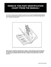
... MANUAL! Please Note: The assembly is packaged separately. if you begin each stage is divided into four stages: 1) frame assembly, 2) press and butterfly arm assembly, 3) cable and pulley assembly, and 4) seat and backrest assembly.
... MANUAL! Please Note: The assembly is packaged separately. if you begin each stage is divided into four stages: 1) frame assembly, 2) press and butterfly arm assembly, 3) cable and pulley assembly, and 4) seat and backrest assembly.
User Manual
Page 26
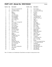
... x 2 3/4" Carriage Bolt 3 1/2" Pulley 3/8" x 3 1/2" Bolt Press Frame 1/4" x 1/2" Screw Weight Bumper Pulley Bracket 3/8" Nylon Locknut 5/16" x 2 1/2" Bolt Long Cable 1/4" x 2 1/4" Screw Weight Weight Pin 2" Square Inner Cap Small Pad Tube Leg Lever 5 1/2" Pad Hand Grip Rocker Arm 3/8" Nylon Jam Nut 3/4" Round Inner Cap 3/8"...1 3/4" Square Inner Cap 10" Pad Press Arm Left Arm Right Arm 1" Round Inner Cap Long Cable Trap 2" Square Outer Cap Chain Cable Clip Lat Bar Top Frame Rear Upright Long "U"-Bracket Short Cable 3/8" x 8" Bolt 5/16" x 6" Bolt 1/2" x 3/4" Spacer Weight Guide Weight Tube Weight ...
... x 2 3/4" Carriage Bolt 3 1/2" Pulley 3/8" x 3 1/2" Bolt Press Frame 1/4" x 1/2" Screw Weight Bumper Pulley Bracket 3/8" Nylon Locknut 5/16" x 2 1/2" Bolt Long Cable 1/4" x 2 1/4" Screw Weight Weight Pin 2" Square Inner Cap Small Pad Tube Leg Lever 5 1/2" Pad Hand Grip Rocker Arm 3/8" Nylon Jam Nut 3/4" Round Inner Cap 3/8"...1 3/4" Square Inner Cap 10" Pad Press Arm Left Arm Right Arm 1" Round Inner Cap Long Cable Trap 2" Square Outer Cap Chain Cable Clip Lat Bar Top Frame Rear Upright Long "U"-Bracket Short Cable 3/8" x 8" Bolt 5/16" x 6" Bolt 1/2" x 3/4" Spacer Weight Guide Weight Tube Weight ...


