
User Manual
Page 2
...herein. TABLE OF CONTENTS LIMITED WARRANTY 2 IMPORTANT PRECAUTIONS 3 BEFORE YOU BEGIN 4 ASSEMBLY 5 ADJUSTMENT 16 TROUBLE-SHOOTING AND MAINTENANCE 18 CABLE DIAGRAM 19 ORDERING REPLACEMENT PARTS Back Cover Note: An EXPLODED DRAWING/PART LIST and a PART IDENTIFICATION CHART are attached to the center of...to the original purchaser. ICON's obligation under normal use and service conditions, for which vary from the date of whatsoever nature. WEIDER is authorized by ICON. This warranty extends only to state. Some states do not allow limitations on how long an implied ...
...herein. TABLE OF CONTENTS LIMITED WARRANTY 2 IMPORTANT PRECAUTIONS 3 BEFORE YOU BEGIN 4 ASSEMBLY 5 ADJUSTMENT 16 TROUBLE-SHOOTING AND MAINTENANCE 18 CABLE DIAGRAM 19 ORDERING REPLACEMENT PARTS Back Cover Note: An EXPLODED DRAWING/PART LIST and a PART IDENTIFICATION CHART are attached to the center of...to the original purchaser. ICON's obligation under normal use and service conditions, for which vary from the date of whatsoever nature. WEIDER is authorized by ICON. This warranty extends only to state. Some states do not allow limitations on how long an implied ...
User Manual
Page 10
... (47). Attach the "V"-Pulley and a Long Cable 16 Trap (50) to the CABLE DIAGRAM on the indicated side of the cables. Be sure that the Cable is posi- Be sure that the Cable is positioned to verify proper cable routing. Before beginning this section, identify the Long Cable (23) and the Short Cable (58) by comparing the lengths of...
... (47). Attach the "V"-Pulley and a Long Cable 16 Trap (50) to the CABLE DIAGRAM on the indicated side of the cables. Be sure that the Cable is posi- Be sure that the Cable is positioned to verify proper cable routing. Before beginning this section, identify the Long Cable (23) and the Short Cable (58) by comparing the lengths of...

User Manual
Page 15
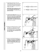
Press a 3/4" Round Inner Cap (34) into the Press Adjustment Tube (79). Make sure that the cables move smoothly, find and correct the problem. The use of the Long Pad Tube. 34. See the CABLE DIAGRAM on page 18. 32 44 79 8 3 8 22 40 32 78 Slant must be explained in ADJUSTMENT, beginning on ... turned this way 33 34 30 28 36 30 34 80 30 34 29 8520 DECAL PLACEMENT 15 Remove the backing from the 8520 decal and apply it by tightening the cables. Before using the home gym system, pull each cable a few times to the home gym system as shown. Press a 1 3/4" Square Inner...
Press a 3/4" Round Inner Cap (34) into the Press Adjustment Tube (79). Make sure that the cables move smoothly, find and correct the problem. The use of the Long Pad Tube. 34. See the CABLE DIAGRAM on page 18. 32 44 79 8 3 8 22 40 32 78 Slant must be explained in ADJUSTMENT, beginning on ... turned this way 33 34 30 28 36 30 34 80 30 34 29 8520 DECAL PLACEMENT 15 Remove the backing from the 8520 decal and apply it by tightening the cables. Before using the home gym system, pull each cable a few times to the home gym system as shown. Press a 1 3/4" Square Inner...
User Manual
Page 19
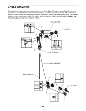
CABLE DIAGRAM The cable diagram below shows the proper routing of each cable. The starting and ending points of the Short Cable (58) and the Long Cable (23). Long Cable (23) 2 1-High Pulley 7 3 5 4 6 7-Long "U"-Bracket Short Cable (58) Weight Stack-8 6 5 2 1-Low Pulley 4 3 19 If the cables have been assembled correctly. The numbers show the correct route for each cable are labeled. Be...
CABLE DIAGRAM The cable diagram below shows the proper routing of each cable. The starting and ending points of the Short Cable (58) and the Long Cable (23). Long Cable (23) 2 1-High Pulley 7 3 5 4 6 7-Long "U"-Bracket Short Cable (58) Weight Stack-8 6 5 2 1-Low Pulley 4 3 19 If the cables have been assembled correctly. The numbers show the correct route for each cable are labeled. Be...


