
User Manual
Page 1
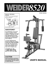
... PENDING USER'S MANUAL If you have questions, or find there are committed to you complete satisfaction through direct assistance from our factory. Model No. As a manufacturer, we are missing or damaged parts, we will provide immediate assistance, free of charge to providing complete customer satisfaction. WESY85200 Serial No. (Write the serial number in this manual before using this manual for reference.) Serial Number Decal...
... PENDING USER'S MANUAL If you have questions, or find there are committed to you complete satisfaction through direct assistance from our factory. Model No. As a manufacturer, we are missing or damaged parts, we will provide immediate assistance, free of charge to providing complete customer satisfaction. WESY85200 Serial No. (Write the serial number in this manual before using this manual for reference.) Serial Number Decal...
User Manual
Page 2
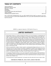
... above is authorized by ICON. TABLE OF CONTENTS LIMITED WARRANTY 2 IMPORTANT PRECAUTIONS 3 BEFORE YOU BEGIN 4 ASSEMBLY 5 ADJUSTMENT 16 TROUBLE-SHOOTING AND MAINTENANCE 18 CABLE DIAGRAM 19 ORDERING REPLACEMENT PARTS Back Cover Note: An EXPLODED DRAWING/PART LIST and a PART IDENTIFICATION CHART are attached to the center of this product to be free from defects in workmanship and material, under this warranty is limited to replacing or repairing, at ICON's option, the product at...
... above is authorized by ICON. TABLE OF CONTENTS LIMITED WARRANTY 2 IMPORTANT PRECAUTIONS 3 BEFORE YOU BEGIN 4 ASSEMBLY 5 ADJUSTMENT 16 TROUBLE-SHOOTING AND MAINTENANCE 18 CABLE DIAGRAM 19 ORDERING REPLACEMENT PARTS Back Cover Note: An EXPLODED DRAWING/PART LIST and a PART IDENTIFICATION CHART are attached to the center of this product to be free from defects in workmanship and material, under this warranty is limited to replacing or repairing, at ICON's option, the product at...
User Manual
Page 3
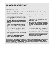
... lat bar from the home gym system when performing an exercise that the cables are raised. Always wear athletic shoes for protection. 5. Always stand on the pulleys at any time while exercising, stop immediately and make sure that does not use of this product. 3 If the cables bind while you feel pain or dizziness at all parts often. WARNING: Before beginning this manual...
... lat bar from the home gym system when performing an exercise that the cables are raised. Always wear athletic shoes for protection. 5. Always stand on the pulleys at any time while exercising, stop immediately and make sure that does not use of this product. 3 If the cables bind while you feel pain or dizziness at all parts often. WARNING: Before beginning this manual...
User Manual
Page 4
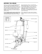
... Friday, 6 a.m. The serial number can be found on a decal attached to tone your body, build dramatic muscle size and strength, or improve your cardiovascular system, the WEIDER® 8510 will help us assist you want. If you for selecting the versatile WEIDER® 8520 Home Gym System. High Pulley Station Lat Bar Butterfly Arms Backrest Leg Press Plate Leg Lever Low Pulley Station Foot Plate 4 Press Arm Seat Weight Stack Weight Pin Whether your...
... Friday, 6 a.m. The serial number can be found on a decal attached to tone your body, build dramatic muscle size and strength, or improve your cardiovascular system, the WEIDER® 8510 will help us assist you want. If you for selecting the versatile WEIDER® 8520 Home Gym System. High Pulley Station Lat Bar Butterfly Arms Backrest Leg Press Plate Leg Lever Low Pulley Station Foot Plate 4 Press Arm Seat Weight Stack Weight Pin Whether your...
User Manual
Page 5
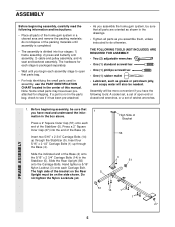
... (4) onto the 5/16" x 2 3/4" Carriage Bolts (14) in a cleared area and remove the packing materials; Slide the Rear Upright (56) onto the Carriage Bolts. Do not tighten the Nylon Locknuts yet. 1 5 51 High Side of the Base (4). FRAME ASSEMBLY 1. Press a 2" Square Inner Cap (27) into four stages: 1) frame assembly, 2) press and butterfly arm assembly, 3) cable and pulley assembly, and 4) seat and backrest assembly. Hand tighten a 5/16" Nylon Locknut (3) onto...
... (4) onto the 5/16" x 2 3/4" Carriage Bolts (14) in a cleared area and remove the packing materials; Slide the Rear Upright (56) onto the Carriage Bolts. Do not tighten the Nylon Locknuts yet. 1 5 51 High Side of the Base (4). FRAME ASSEMBLY 1. Press a 2" Square Inner Cap (27) into four stages: 1) frame assembly, 2) press and butterfly arm assembly, 3) cable and pulley assembly, and 4) seat and backrest assembly. Hand tighten a 5/16" Nylon Locknut (3) onto...
User Manual
Page 6
... 6 Attach the Top Frame (55) to the Front Upright (42) and the Rear Upright (56) with four 5/16" x 2 3/4" Bolts (11), four 5/16" Flat Washers (8), and four 5/16" Nylon Locknuts (3). Press a 1 3/4" Square Inner Cap (44) into the top of the Weights are turned so the pin grooves are on the Top Frame. Do not tighten the Nylon Locknuts yet. 42 FRAME ASSEMBLY...
... 6 Attach the Top Frame (55) to the Front Upright (42) and the Rear Upright (56) with four 5/16" x 2 3/4" Bolts (11), four 5/16" Flat Washers (8), and four 5/16" Nylon Locknuts (3). Press a 1 3/4" Square Inner Cap (44) into the top of the Weights are turned so the pin grooves are on the Top Frame. Do not tighten the Nylon Locknuts yet. 42 FRAME ASSEMBLY...
User Manual
Page 8
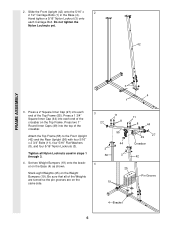
... lower end of each Arm. Tap two 1" Retainers (69) and a 1" Round Cover Cap (70) onto the right axle. Press a 1 3/4" Square Inner Cap (44) into the lower ends of the Press Frame (17) with a 3/8" x 2 1/2" Bolt (7) and a 3/8" Nylon Locknut (21). 8 31 44 49 46 22 9 50 6 Welded Brackets 48 3 17 7 50 6 21 44 49 46 47 ARM ASSEMBLY 10. Attach a "V"-Pulley (6) and a Long Cable...
... lower end of each Arm. Tap two 1" Retainers (69) and a 1" Round Cover Cap (70) onto the right axle. Press a 1 3/4" Square Inner Cap (44) into the lower ends of the Press Frame (17) with a 3/8" x 2 1/2" Bolt (7) and a 3/8" Nylon Locknut (21). 8 31 44 49 46 22 9 50 6 Welded Brackets 48 3 17 7 50 6 21 44 49 46 47 ARM ASSEMBLY 10. Attach a "V"-Pulley (6) and a Long Cable...
User Manual
Page 9
... 36 17 44 73 36 65 3 ARM ASSEMBLY 12. Attach the Leg Lever (29) to the Rocker Arm (32) with a 1/2" Tap Screw (65). 12 Lubricate a 3/8" x 3 1/4" Bolt (35). Press a 1 3/4" Square Inner Cap (44) into the 11 Seat Frame (36). Attach a Bumper (73) to the Base (4) with a 1/2" Tap Screw (65). Attach the Rocker arm (32) to the Rocker Arm (32) with the 3/8" x 2 1/2" Bolt and a 3/8" Nylon Jam Nut (33...
... 36 17 44 73 36 65 3 ARM ASSEMBLY 12. Attach the Leg Lever (29) to the Rocker Arm (32) with a 1/2" Tap Screw (65). 12 Lubricate a 3/8" x 3 1/4" Bolt (35). Press a 1 3/4" Square Inner Cap (44) into the 11 Seat Frame (36). Attach a Bumper (73) to the Base (4) with a 1/2" Tap Screw (65). Attach the Rocker arm (32) to the Rocker Arm (32) with the 3/8" x 2 1/2" Bolt and a 3/8" Nylon Jam Nut (33...
User Manual
Page 10
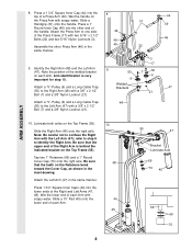
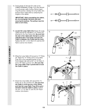
... Left Arm (47). Tighten the 3/8" x 2 1/2" Bolt (7) and the 3/8" Nylon Locknut (not shown). 7 6 50 42 23 21 6 7 50 47 23 10 Route the Long Cable (23) around the "V"- 17 Pulley (6) on the Front Upright (42) with the ball is posi- tioned to turn freely. 14 23 58 15. Attach the "V"-Pulley and a Long Cable 16 Trap (50) to the Top Frame (55). Locate...
... Left Arm (47). Tighten the 3/8" x 2 1/2" Bolt (7) and the 3/8" Nylon Locknut (not shown). 7 6 50 42 23 21 6 7 50 47 23 10 Route the Long Cable (23) around the "V"- 17 Pulley (6) on the Front Upright (42) with the ball is posi- tioned to turn freely. 14 23 58 15. Attach the "V"-Pulley and a Long Cable 16 Trap (50) to the Top Frame (55). Locate...
User Manual
Page 11
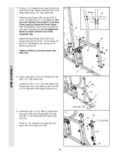
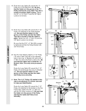
Route the Long Cable (23) around the 3 1/2" Pulley (15) attached to the bracket on the Right Arm (48). See the inset drawing. Be sure that the Cable and Pulley move freely. 19 68 66 20 12 23 15 20. It is in the Long "U"-Bracket (57) with a 3/8" x 2" Bolt (12) and a 3/8" Nylon Locknut (21). CABLE ASSEMBLY 18. Tighten the 3/8" x 2 1/2" Bolt (7) and the 3/8" Nylon Locknut (not...
Route the Long Cable (23) around the 3 1/2" Pulley (15) attached to the bracket on the Right Arm (48). See the inset drawing. Be sure that the Cable and Pulley move freely. 19 68 66 20 12 23 15 20. It is in the Long "U"-Bracket (57) with a 3/8" x 2" Bolt (12) and a 3/8" Nylon Locknut (21). CABLE ASSEMBLY 18. Tighten the 3/8" x 2 1/2" Bolt (7) and the 3/8" Nylon Locknut (not...
User Manual
Page 12
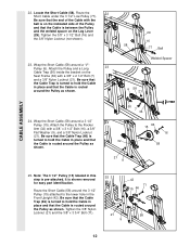
CABLE ASSEMBLY 22. Tighten the 3/8" x 3 1/2" Bolt (16) and the 3/8" Nylon Locknut (not shown). 23. Pulley (6). Attach the Pulley to the Rocker Arm (32) with a 3/8" x 2 1/2" Bolt (7) and a 3/8" Nylon Locknut (21). Be sure that the Cable Trap (66) is turned to the lower hole in place and that the Cable is routed around the Pulley as shown. Attach the Pulley and a Long 23 Cable Trap (50) inside the bracket on the...
CABLE ASSEMBLY 22. Tighten the 3/8" x 3 1/2" Bolt (16) and the 3/8" Nylon Locknut (not shown). 23. Pulley (6). Attach the Pulley to the Rocker Arm (32) with a 3/8" x 2 1/2" Bolt (7) and a 3/8" Nylon Locknut (21). Be sure that the Cable Trap (66) is turned to the lower hole in place and that the Cable is routed around the Pulley as shown. Attach the Pulley and a Long 23 Cable Trap (50) inside the bracket on the...
User Manual
Page 13
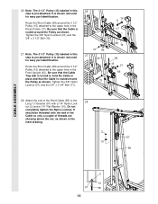
... that the Cable is shown removed for easy part identification. It is routed around the 3 1/2" Pulley (15) attached to the upper hole in the inset drawing. 2 57 10 58 CABLE ASSEMBLY 2 10 57 58 13 Attach the end of threads are showing above the nut, as shown. Tighten the 3/8" Nylon Locknut (21) and the 3/8" x 3 1/2" Bolt (16). 27. Route the Short Cable (58) around...
... that the Cable is shown removed for easy part identification. It is routed around the 3 1/2" Pulley (15) attached to the upper hole in the inset drawing. 2 57 10 58 CABLE ASSEMBLY 2 10 57 58 13 Attach the end of threads are showing above the nut, as shown. Tighten the 3/8" Nylon Locknut (21) and the 3/8" x 3 1/2" Bolt (16). 27. Route the Short Cable (58) around...

User Manual
Page 14
... Upright (42) with a 1/4" Flat Washer (10) onto the Carriage Bolt. Insert the 1/4" x 2 1/2" Carriage Bolt (38) into 31 the center hole in the Seat Frame (36). Tighten a 1/4" Nylon Locknut (2) with two 1/4" x 2 1/2" Screws (43) and 30 two 1/4" Flat Washers (10). 23 10 2 67 42 41 43 10 SEAT ASSEMBLY 31. Attach the Long Cable (23) to the Weight Tube (63) with two 1/4" x 1/2" Screws (18). Attach...
... Upright (42) with a 1/4" Flat Washer (10) onto the Carriage Bolt. Insert the 1/4" x 2 1/2" Carriage Bolt (38) into 31 the center hole in the Seat Frame (36). Tighten a 1/4" Nylon Locknut (2) with two 1/4" x 2 1/2" Screws (43) and 30 two 1/4" Flat Washers (10). 23 10 2 67 42 41 43 10 SEAT ASSEMBLY 31. Attach the Long Cable (23) to the Weight Tube (63) with two 1/4" x 1/2" Screws (18). Attach...

User Manual
Page 15
... Rocker Arm (32). Before using the home gym system, pull each end of the Long Pad Tube (80). IMPORTANT: If the cables are not properly installed, they may be turned this manual for proper cable routing. Attach the Press Plate (78) to the home gym system as shown. Press a 3/4" Round Inner Cap into each end of the cables does not move smoothly over the pulleys. If one set of...
... Rocker Arm (32). Before using the home gym system, pull each end of the Long Pad Tube (80). IMPORTANT: If the cables are not properly installed, they may be turned this manual for proper cable routing. Attach the Press Plate (78) to the home gym system as shown. Press a 3/4" Round Inner Cap into each end of the cables does not move smoothly over the pulleys. If one set of...
User Manual
Page 16
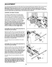
... using the low pulley station (see how the home gym system should be set up for the exercise to find the approximate amount of the Weight Pin is in the correct starting position for the exercise to 106.5 pounds, in the same manner. CHANGING THE WEIGHT SETTING To change the weight setting of 12.5 pounds. The Nylon Strap (39) can be attached between the Lat Bar and the Long Cable with a Cable...
... using the low pulley station (see how the home gym system should be set up for the exercise to find the approximate amount of the Weight Pin is in the correct starting position for the exercise to 106.5 pounds, in the same manner. CHANGING THE WEIGHT SETTING To change the weight setting of 12.5 pounds. The Nylon Strap (39) can be attached between the Lat Bar and the Long Cable with a Cable...
User Manual
Page 17
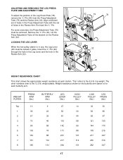
... hole in the Rocker Arm (32). 32 79 78 40 32 40 29 WEIGHT RESISTANCE CHART This chart shows the approximate weight resistance at each butterfly arm. ADJUSTING AND REMOVING THE LEG PRESS PLATE AND ADJUSTMENT TUBE To adjust the position of holes in place. The other numbers refer to the 6.5 lb. Re-insert the "L"-Pin. For some exercises, the Press Adjustment Tube (79) must be removed. Weight resistance shown for each...
... hole in the Rocker Arm (32). 32 79 78 40 32 40 29 WEIGHT RESISTANCE CHART This chart shows the approximate weight resistance at each butterfly arm. ADJUSTING AND REMOVING THE LEG PRESS PLATE AND ADJUSTMENT TUBE To adjust the position of holes in place. The other numbers refer to the 6.5 lb. Re-insert the "L"-Pin. For some exercises, the Press Adjustment Tube (79) must be removed. Weight resistance shown for each...
User Manual
Page 18
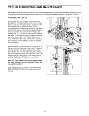
...), Pulley, and "U"-Bracket. TIGHTENING THE CABLES Woven cable, the type of this you use solvents. Do not use the home gym system. TROUBLE-SHOOTING AND MAINTENANCE Inspect and tighten all parts each time you may have become twisted. The home gym system can be tightened. Re-attach the Pulley and Cable Trap. Slack can be lifted off the pulleys often, the cable may need to remove the Small "U"-Bracket (67) from the Weight...
...), Pulley, and "U"-Bracket. TIGHTENING THE CABLES Woven cable, the type of this you use solvents. Do not use the home gym system. TROUBLE-SHOOTING AND MAINTENANCE Inspect and tighten all parts each time you may have become twisted. The home gym system can be tightened. Re-attach the Pulley and Cable Trap. Slack can be lifted off the pulleys often, the cable may need to remove the Small "U"-Bracket (67) from the Weight...
User Manual
Page 20
The MODEL NUMBER of the product (WEIDER® 8520 Home Gym System). 3. The SERIAL NUMBER of the product (see the PART LIST and EXPLODED DRAWING at 1-800-999-3756, Monday through Friday, 6 a.m. ORDERING REPLACEMENT PARTS To order replacement parts, simply call our Customer Service Department toll-free at the center of this manual). 4. until 6 p.m. Part No. 132714 R0896A Printed in Canada © 1996 ICON Health & Fitness, Inc. The NAME of the product...
The MODEL NUMBER of the product (WEIDER® 8520 Home Gym System). 3. The SERIAL NUMBER of the product (see the PART LIST and EXPLODED DRAWING at 1-800-999-3756, Monday through Friday, 6 a.m. ORDERING REPLACEMENT PARTS To order replacement parts, simply call our Customer Service Department toll-free at the center of this manual). 4. until 6 p.m. Part No. 132714 R0896A Printed in Canada © 1996 ICON Health & Fitness, Inc. The NAME of the product...
User Manual
Page 21
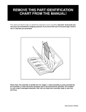
... to help you identify the small parts used in the parts bags, check to open that parts bag. Wait until you cannot find a part in assembly. REMOVE THIS PART IDENTIFICATION CHART FROM THE MANUAL! if you begin each stage is packaged separately. This chart is divided into four stages: 1) frame assembly, 2) press and butterfly arm assembly, 3) cable and pulley assembly, and 4) seat and backrest assembly. The hardware for shipping purposes; WESY85200...
... to help you identify the small parts used in the parts bags, check to open that parts bag. Wait until you cannot find a part in assembly. REMOVE THIS PART IDENTIFICATION CHART FROM THE MANUAL! if you begin each stage is packaged separately. This chart is divided into four stages: 1) frame assembly, 2) press and butterfly arm assembly, 3) cable and pulley assembly, and 4) seat and backrest assembly. The hardware for shipping purposes; WESY85200...
User Manual
Page 26
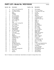
...2" Square Outer Cap Chain Cable Clip Lat Bar Top Frame Rear Upright Long "U"-Bracket Short Cable 3/8" x 8" Bolt 5/16" x 6" Bolt 1/2" x 3/4" Spacer Weight Guide Weight Tube Weight Tube Bumper 1/2" Tap Screw Cable Trap Small "U"-Bracket 5/16" x 5" Bolt 1" Retainer 1" Round Cover Cap 3/8" x 3 3/4" Bolt 5/16" x 1 3/4" Bolt Bumper 1 1/8" x 2 1/2" Plastic Bushing 1" x 7/8" Plastic Bushing Top Weight 3 1/2" Low Pulley Leg Press Plate Press Adjustment Tube Long Pad Tube User's Manual Exercise Poster Note: "#" indicates a non-illustrated part. WESY85200 R0896A Key No. Specifications are subject to...
...2" Square Outer Cap Chain Cable Clip Lat Bar Top Frame Rear Upright Long "U"-Bracket Short Cable 3/8" x 8" Bolt 5/16" x 6" Bolt 1/2" x 3/4" Spacer Weight Guide Weight Tube Weight Tube Bumper 1/2" Tap Screw Cable Trap Small "U"-Bracket 5/16" x 5" Bolt 1" Retainer 1" Round Cover Cap 3/8" x 3 3/4" Bolt 5/16" x 1 3/4" Bolt Bumper 1 1/8" x 2 1/2" Plastic Bushing 1" x 7/8" Plastic Bushing Top Weight 3 1/2" Low Pulley Leg Press Plate Press Adjustment Tube Long Pad Tube User's Manual Exercise Poster Note: "#" indicates a non-illustrated part. WESY85200 R0896A Key No. Specifications are subject to...


