
User Manual
Page 2
...do not allow limitations on how long an implied warranty lasts. TABLE OF CONTENTS LIMITED WARRANTY 2 IMPORTANT PRECAUTIONS 3 BEFORE YOU BEGIN 4 ASSEMBLY 5 ADJUSTMENT 16 TROUBLE-SHOOTING AND MAINTENANCE 18 CABLE DIAGRAM 19 ORDERING REPLACEMENT PARTS Back Cover Note: An EXPLODED DRAWING/PART LIST and ...caused by or attributable to you specific legal rights. ICON HEALTH & FITNESS, INC., 1500 S. 1000 W., LOGAN, UT 84321-9813 2 WEIDER is authorized by an ICON authorized service center, products used as store display models. This warranty does not extend to any economic loss, ...
...do not allow limitations on how long an implied warranty lasts. TABLE OF CONTENTS LIMITED WARRANTY 2 IMPORTANT PRECAUTIONS 3 BEFORE YOU BEGIN 4 ASSEMBLY 5 ADJUSTMENT 16 TROUBLE-SHOOTING AND MAINTENANCE 18 CABLE DIAGRAM 19 ORDERING REPLACEMENT PARTS Back Cover Note: An EXPLODED DRAWING/PART LIST and ...caused by or attributable to you specific legal rights. ICON HEALTH & FITNESS, INC., 1500 S. 1000 W., LOGAN, UT 84321-9813 2 WEIDER is authorized by an ICON authorized service center, products used as store display models. This warranty does not extend to any economic loss, ...
User Manual
Page 4
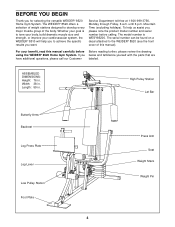
... help you to the WEIDER® 8520 (see the front cover of the body. For your cardiovascular system, the WEIDER® 8510 will help us assist you for selecting the versatile WEIDER® 8520 Home Gym System. Mountain...number and serial number before Before reading further, please review the drawing using the WEIDER® 8520 Home Gym System. If you want. High Pulley Station Lat Bar Butterfly Arms ... Plate 4 Press Arm Seat Weight Stack Weight Pin Length: 59 in . The WEIDER® 8520 offers a selection of weight stations designed to tone your body, build dramatic muscle size...
... help you to the WEIDER® 8520 (see the front cover of the body. For your cardiovascular system, the WEIDER® 8510 will help us assist you for selecting the versatile WEIDER® 8520 Home Gym System. Mountain...number and serial number before Before reading further, please review the drawing using the WEIDER® 8520 Home Gym System. If you want. High Pulley Station Lat Bar Butterfly Arms ... Plate 4 Press Arm Seat Weight Stack Weight Pin Length: 59 in . The WEIDER® 8520 offers a selection of weight stations designed to tone your body, build dramatic muscle size...
User Manual
Page 5
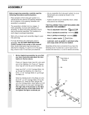
...16" x 2 3/4" Carriage Bolts (14) in a cleared area and remove the packing materials; THE FOLLOWING TOOLS (NOT INCLUDED) ARE REQUIRED FOR ASSEMBLY: • Two (2) adjustable wrenches • One (1) standard screwdriver • One (1) phillips screwdriver • One (1) rubber mallet • ... 14 1 4 1 27 5 Press a 2" Square Inner Cap (27) into four stages: 1) frame assembly, 2) press and butterfly arm assembly, 3) cable and pulley assembly, and 4) seat and backrest assembly. Slide the indicated end of the Base (4). Hand tighten a 5/16" Nylon Locknut (3) onto each end...
...16" x 2 3/4" Carriage Bolts (14) in a cleared area and remove the packing materials; THE FOLLOWING TOOLS (NOT INCLUDED) ARE REQUIRED FOR ASSEMBLY: • Two (2) adjustable wrenches • One (1) standard screwdriver • One (1) phillips screwdriver • One (1) rubber mallet • ... 14 1 4 1 27 5 Press a 2" Square Inner Cap (27) into four stages: 1) frame assembly, 2) press and butterfly arm assembly, 3) cable and pulley assembly, and 4) seat and backrest assembly. Slide the indicated end of the Base (4). Hand tighten a 5/16" Nylon Locknut (3) onto each end...
User Manual
Page 6
... Groove 19 4-Bracket 6 Set two Weight Bumpers (19) onto the bracket on the Weight Bumpers (19). Do not tighten the Nylon Locknuts yet. 42 FRAME ASSEMBLY 3 4 1 3. Tighten all of the Top Frame (55). Press a 1 3/4" Square Inner Cap (44) into each end of the crossbar. Be sure that all Nylon Locknuts used...
... Groove 19 4-Bracket 6 Set two Weight Bumpers (19) onto the bracket on the Weight Bumpers (19). Do not tighten the Nylon Locknuts yet. 42 FRAME ASSEMBLY 3 4 1 3. Tighten all of the Top Frame (55). Press a 1 3/4" Square Inner Cap (44) into each end of the crossbar. Be sure that all Nylon Locknuts used...
User Manual
Page 7
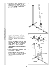
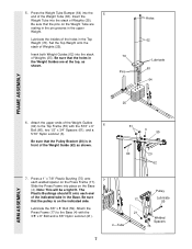
...the Base (4). Attach the Press Frame (17) to the Top Frame (55) with the 3/8" x 8" Bolt and a 3/8" Nylon Locknut (21). 21 4 -Tube Welded Spacers 75 7 ARM ASSEMBLY Set the Top Weight onto the stack of the Weight Guides (62) to the Base (4) with the 5/16" x 6" 6 Bolt (60), two 1/2" x 3/4" Spacers (61), and a...of Weights (25). Slide the Press Frame into the stack of the Weight Guide (62) as shown. 76 Pins Holes 62 Lubricate 63 64 FRAME ASSEMBLY 25 6. Be sure that the Pulley Bracket (20) is on the Press Frame (17). Be sure that the pulley is in the upper Weight...
...the Base (4). Attach the Press Frame (17) to the Top Frame (55) with the 3/8" x 8" Bolt and a 3/8" Nylon Locknut (21). 21 4 -Tube Welded Spacers 75 7 ARM ASSEMBLY Set the Top Weight onto the stack of the Weight Guides (62) to the Base (4) with the 5/16" x 6" 6 Bolt (60), two 1/2" x 3/4" Spacers (61), and a...of Weights (25). Slide the Press Frame into the stack of the Weight Guide (62) as shown. 76 Pins Holes 62 Lubricate 63 64 FRAME ASSEMBLY 25 6. Be sure that the Pulley Bracket (20) is on the Press Frame (17). Be sure that the pulley is in the upper Weight...
User Manual
Page 8
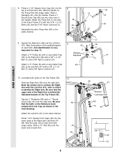
...9. Slide the Right Arm (48) onto the right axle. Tap two 1" Retainers (69) and a 1" Round Cover Cap (70) onto the right axle. Assemble the other end of a Press Arm (46). Arm identification is behind the indicated bracket on the Top Frame (55). Lubricate both axles on the Retainers...a 3/8" x 2 1/2" Bolt (7) and a 3/8" Nylon Locknut (21). 8 31 44 49 46 22 9 50 6 Welded Brackets 48 3 17 7 50 6 21 44 49 46 47 ARM ASSEMBLY 10. Note the position of the Right Arm is very important for step 10. Press a 1 3/4" Square Inner Cap (44) into the lower ends of each...
...9. Slide the Right Arm (48) onto the right axle. Tap two 1" Retainers (69) and a 1" Round Cover Cap (70) onto the right axle. Assemble the other end of a Press Arm (46). Arm identification is behind the indicated bracket on the Top Frame (55). Lubricate both axles on the Retainers...a 3/8" x 2 1/2" Bolt (7) and a 3/8" Nylon Locknut (21). 8 31 44 49 46 22 9 50 6 Welded Brackets 48 3 17 7 50 6 21 44 49 46 47 ARM ASSEMBLY 10. Note the position of the Right Arm is very important for step 10. Press a 1 3/4" Square Inner Cap (44) into the lower ends of each...
User Manual
Page 9
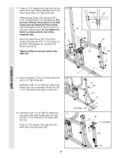
... and two 5/16" Nylon Locknuts (3). 11 Tighten all Nylon Locknuts used in the Base (4). Hand-tighten a 5/16" Nylon Locknut (3) 42 onto each end of this assembly step. 3 Attach the Seat Frame (36) to the Rocker Arm (32) with a 1/2" Tap Screw (65). 12 Lubricate a 3/8" x 3 1/4" Bolt (35). ... until the end of the Leg Lever (29). 4 Lubricate-35 13 44 32 7-Lubricate 33 29 44 9 Bracket 36 17 44 73 36 65 3 ARM ASSEMBLY 12. See the inset drawing. Lubricate a 3/8" x 2 1/2" Bolt (7). 11. Press a 1 3/4" Square Inner Cap (44) into the 11 Seat Frame (36). Press a 1 ...
... and two 5/16" Nylon Locknuts (3). 11 Tighten all Nylon Locknuts used in the Base (4). Hand-tighten a 5/16" Nylon Locknut (3) 42 onto each end of this assembly step. 3 Attach the Seat Frame (36) to the Rocker Arm (32) with a 1/2" Tap Screw (65). 12 Lubricate a 3/8" x 3 1/4" Bolt (35). ... until the end of the Leg Lever (29). 4 Lubricate-35 13 44 32 7-Lubricate 33 29 44 9 Bracket 36 17 44 73 36 65 3 ARM ASSEMBLY 12. See the inset drawing. Lubricate a 3/8" x 2 1/2" Bolt (7). 11. Press a 1 3/4" Square Inner Cap (44) into the 11 Seat Frame (36). Press a 1 ...
User Manual
Page 10
IMPORTANT: While assembling the cables, do not overtighten the bolts and nuts securing the pulleys. Locate the Long Cable (23). Route the Long Cable around a "V"-Pulley (6). Wrap the ... 23 10 Be sure that the Cable is in place. Be sure that the Long Cable Trap is between the Pulley and the hook. CABLE ASSEMBLY 14. During steps 15 through 29, refer to turn freely. 14 23 58 15.
IMPORTANT: While assembling the cables, do not overtighten the bolts and nuts securing the pulleys. Locate the Long Cable (23). Route the Long Cable around a "V"-Pulley (6). Wrap the ... 23 10 Be sure that the Cable is in place. Be sure that the Long Cable Trap is between the Pulley and the hook. CABLE ASSEMBLY 14. During steps 15 through 29, refer to turn freely. 14 23 58 15.
User Manual
Page 11
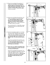
... inset drawing. Bracket. Be sure that the Long Cable Trap (50) is pre-attached. Tighten the 3/8" x 2" Bolt (12) 55 and the 3/8" Nylon Locknut (21). CABLE ASSEMBLY 18. Pulley and that the Cable is in this 21 step is turned to hold the Cable in the groove of the "V"- Route the Long...
... inset drawing. Bracket. Be sure that the Long Cable Trap (50) is pre-attached. Tighten the 3/8" x 2" Bolt (12) 55 and the 3/8" Nylon Locknut (21). CABLE ASSEMBLY 18. Pulley and that the Cable is in this 21 step is turned to hold the Cable in the groove of the "V"- Route the Long...
User Manual
Page 12
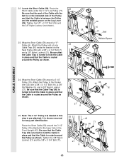
... Arm (32) with a 3/8" x 2 1/2" Bolt (7) and a 3/8" Nylon Locknut (21). Note: The 3 1/2" Pulley (15) labeled in place and that the Cable is routed around a 3 1/2" Pulley (15). CABLE ASSEMBLY 22. Route the 22 Short Cable under the 3 1/2" Low Pulley (77). Route the Short Cable (58) around a "V"- It is pre-attached. Locate the Short Cable...
... Arm (32) with a 3/8" x 2 1/2" Bolt (7) and a 3/8" Nylon Locknut (21). Note: The 3 1/2" Pulley (15) labeled in place and that the Cable is routed around a 3 1/2" Pulley (15). CABLE ASSEMBLY 22. Route the 22 Short Cable under the 3 1/2" Low Pulley (77). Route the Short Cable (58) around a "V"- It is pre-attached. Locate the Short Cable...
User Manual
Page 13
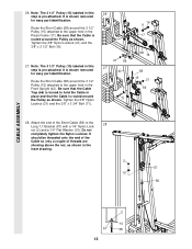
... nut, as shown. Route the Short Cable (58) around the 3 1/2" Pulley (15) attached to the upper hole in the inset drawing. 2 57 10 58 CABLE ASSEMBLY 2 10 57 58 13 Tighten the 3/8" Nylon Locknut (21) and the 3/8" x 3 1/2" Bolt (16). 27. Be sure that the Cable is routed around the 3 1/2" Pulley (15...
... nut, as shown. Route the Short Cable (58) around the 3 1/2" Pulley (15) attached to the upper hole in the inset drawing. 2 57 10 58 CABLE ASSEMBLY 2 10 57 58 13 Tighten the 3/8" Nylon Locknut (21) and the 3/8" x 3 1/2" Bolt (16). 27. Be sure that the Cable is routed around the 3 1/2" Pulley (15...

User Manual
Page 14
... Bolt (38) into 31 the center hole in the Seat Frame (36). Attach the other end of turns, as shown in the inset drawing. CABLE ASSEMBLY 29. Do not com- pletely tighten the Nylon Locknut. Insert the 1/4" x 2 1/2" Carriage Bolt (38) into the indicated hole in the Seat Plate (37). ...Tighten a 1/4" Nylon Locknut (2) with two 1/4" x 2 1/2" Screws (43) and 30 two 1/4" Flat Washers (10). 23 10 2 67 42 41 43 10 SEAT ASSEMBLY 31. It should be threaded onto the end of the Cable only a couple of the Seat (13) to the Seat (13) with a 1/4" Nylon Locknut (2) and...
... Bolt (38) into 31 the center hole in the Seat Frame (36). Attach the other end of turns, as shown in the inset drawing. CABLE ASSEMBLY 29. Do not com- pletely tighten the Nylon Locknut. Insert the 1/4" x 2 1/2" Carriage Bolt (38) into the indicated hole in the Seat Plate (37). ...Tighten a 1/4" Nylon Locknut (2) with two 1/4" x 2 1/2" Screws (43) and 30 two 1/4" Flat Washers (10). 23 10 2 67 42 41 43 10 SEAT ASSEMBLY 31. It should be threaded onto the end of the Cable only a couple of the Seat (13) to the Seat (13) with a 1/4" Nylon Locknut (2) and...

User Manual
Page 15
.... 34. Slide a 5 1/2" Pad (30) onto each end of the remaining parts will need to the home gym system as shown. Remove the backing from the 8520 decal and apply it to remove it by tightening the cables. Insert the "L"-Pin (40) through the holes. Insert the Long Pad Tube (80) into... correct the problem. Align one of the Short Pad Tube (28). Attach the Press Plate (78) to be damaged when heavy weight is used. SEAT ASSEMBLY 32. Press a 1 3/4" Square Inner Cap (44) into each cable a few times to the Press Adjustment Tube (79) with the holes in the Press Adjustment Tube...
.... 34. Slide a 5 1/2" Pad (30) onto each end of the remaining parts will need to the home gym system as shown. Remove the backing from the 8520 decal and apply it to remove it by tightening the cables. Insert the "L"-Pin (40) through the holes. Insert the Long Pad Tube (80) into... correct the problem. Align one of the Short Pad Tube (28). Attach the Press Plate (78) to be damaged when heavy weight is used. SEAT ASSEMBLY 32. Press a 1 3/4" Square Inner Cap (44) into each cable a few times to the Press Adjustment Tube (79) with the holes in the Press Adjustment Tube...
User Manual
Page 19
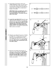
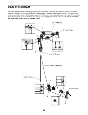
... properly and damage may occur. Long Cable (23) 2 1-High Pulley 7 3 5 4 6 7-Long "U"-Bracket Short Cable (58) Weight Stack-8 6 5 2 1-Low Pulley 4 3 19 If the cables have been assembled correctly. The starting and ending points of the Short Cable (58) and the Long Cable (23). CABLE DIAGRAM The cable diagram below shows the proper...
... properly and damage may occur. Long Cable (23) 2 1-High Pulley 7 3 5 4 6 7-Long "U"-Bracket Short Cable (58) Weight Stack-8 6 5 2 1-Low Pulley 4 3 19 If the cables have been assembled correctly. The starting and ending points of the Short Cable (58) and the Long Cable (23). CABLE DIAGRAM The cable diagram below shows the proper...
User Manual
Page 21
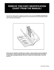
... THIS PART IDENTIFICATION CHART FROM THE MANUAL! Important: Some parts may have been pre-assembled for each assembly stage to see if it has been pre-assembled. Please Note: The assembly is provided to help you identify the small parts used in the parts bags, check... if you begin each stage is packaged separately. WESY85200 R0896A Wait until you cannot find a part in assembly. This chart is divided into four stages: 1) frame assembly, 2) press and butterfly arm assembly, 3) cable and pulley assembly, and 4) seat and backrest assembly. The hardware for shipping purposes;
... THIS PART IDENTIFICATION CHART FROM THE MANUAL! Important: Some parts may have been pre-assembled for each assembly stage to see if it has been pre-assembled. Please Note: The assembly is provided to help you identify the small parts used in the parts bags, check... if you begin each stage is packaged separately. WESY85200 R0896A Wait until you cannot find a part in assembly. This chart is divided into four stages: 1) frame assembly, 2) press and butterfly arm assembly, 3) cable and pulley assembly, and 4) seat and backrest assembly. The hardware for shipping purposes;


