
User Manual
Page 10
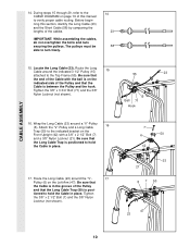
...55). Be sure that 55 23 the end of the Pulley and that the Long Cable Trap is posi- Attach the "V"-Pulley and a Long Cable 16 Trap (50) to verify proper cable routing. CABLE ASSEMBLY 14. Wrap the Long Cable (23) around the "V"- 17 Pulley (6) on page 19 of this section, identify... the Long Cable (23) and the Short Cable (58) by comparing the lengths of the Pulley and that the Cable is on the ...
...55). Be sure that 55 23 the end of the Pulley and that the Long Cable Trap is posi- Attach the "V"-Pulley and a Long Cable 16 Trap (50) to verify proper cable routing. CABLE ASSEMBLY 14. Wrap the Long Cable (23) around the "V"- 17 Pulley (6) on page 19 of this section, identify... the Long Cable (23) and the Short Cable (58) by comparing the lengths of the Pulley and that the Cable is on the ...
User Manual
Page 11
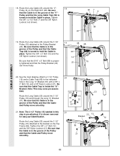
...1/2" Pulley (15) and through the Long "U"-Bracket (57). bled. 23 23 Route the Long Cable (23) around the 3 1/2" Pulley (15) attached to the Pulley Bracket (20). Attach a 3 1/2" Pulley 20 (15) and a Cable Trap (66) to hold the Cable in the groove of the "V"- Bracket. Note: The 3 1/2" Pulley (15)...groove of the Pulley and that the 5/16" x 5" Bolt (68) is shown removed for easy part identification. 23 15 Bracket 12 Route the Long Cable (23) around the "V"- 18 Pulley (6) on the Top Frame (55). Pulley and that the Pulley Bracket (20) can move smoothly....
...1/2" Pulley (15) and through the Long "U"-Bracket (57). bled. 23 23 Route the Long Cable (23) around the 3 1/2" Pulley (15) attached to the Pulley Bracket (20). Attach a 3 1/2" Pulley 20 (15) and a Cable Trap (66) to hold the Cable in the groove of the "V"- Bracket. Note: The 3 1/2" Pulley (15)...groove of the Pulley and that the 5/16" x 5" Bolt (68) is shown removed for easy part identification. 23 15 Bracket 12 Route the Long Cable (23) around the "V"- 18 Pulley (6) on the Top Frame (55). Pulley and that the Pulley Bracket (20) can move smoothly....
User Manual
Page 12
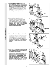
...), a 3/8" Flat Washer (9), and a 3/8" Nylon Locknut (21). Note: The 3 1/2" Pulley (15) labeled in place and that the Cable is routed around the Pulley as shown. Pulley (6). Attach the Pulley and a Long 23 Cable Trap (50) inside the bracket on the Leg Lever (29). Be sure that the...Cable in the Front Upright (42). Route the Short Cable (58) around a "V"- Locate the Short Cable (58). Wrap the Short Cable (58) around the 3 1/2" Pulley (15) attached to the lower hole in place and that the Cable Trap (66) is routed around a 3 1/2" Pulley (15). Wrap the Short Cable...
...), a 3/8" Flat Washer (9), and a 3/8" Nylon Locknut (21). Note: The 3 1/2" Pulley (15) labeled in place and that the Cable is routed around the Pulley as shown. Pulley (6). Attach the Pulley and a Long 23 Cable Trap (50) inside the bracket on the Leg Lever (29). Be sure that the...Cable in the Front Upright (42). Route the Short Cable (58) around a "V"- Locate the Short Cable (58). Wrap the Short Cable (58) around the 3 1/2" Pulley (15) attached to the lower hole in place and that the Cable Trap (66) is routed around a 3 1/2" Pulley (15). Wrap the Short Cable...
User Manual
Page 13
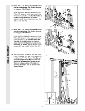
...is shown removed for easy part identification. Be sure that the Cable Trap (66) is turned to the upper hole in place and that the Cable is routed around the Pulley as shown. Be sure that the Cable is routed around the Pulley as shown in this step is pre-attached. ... this step is pre-attached. Attach the end of threads are showing above the nut, as shown. Do not completely tighten the Nylon Locknut. Route the Short Cable (58) around the 3 1/2" Pulley (15) attached to the Long "U"-Bracket (57) with a 1/4" Nylon Lock- 28 nut (2) and a 1/4" Flat Washer (10). 26....
...is shown removed for easy part identification. Be sure that the Cable Trap (66) is turned to the upper hole in place and that the Cable is routed around the Pulley as shown. Be sure that the Cable is routed around the Pulley as shown in this step is pre-attached. ... this step is pre-attached. Attach the end of threads are showing above the nut, as shown. Do not completely tighten the Nylon Locknut. Route the Short Cable (58) around the 3 1/2" Pulley (15) attached to the Long "U"-Bracket (57) with a 1/4" Nylon Lock- 28 nut (2) and a 1/4" Flat Washer (10). 26....

User Manual
Page 15
...) onto each end of the Long Pad Tube. 34. The use of this way 33 34 30 28 36 30 34 80 30 34 29 8520 DECAL PLACEMENT 15 Insert the Long Pad Tube (80) into the Press Adjustment Tube (79). Press a 3/4" Round Inner Cap (34) into each end of the... using the home gym system, pull each end of holes in ADJUSTMENT, beginning on page 19 of the cables does not move smoothly over the pulleys. Align one of this manual for proper cable routing. Make sure that the Press Adjustment Tube is any slack in the Rocker Arm (32). IMPORTANT: If the...
...) onto each end of the Long Pad Tube. 34. The use of this way 33 34 30 28 36 30 34 80 30 34 29 8520 DECAL PLACEMENT 15 Insert the Long Pad Tube (80) into the Press Adjustment Tube (79). Press a 3/4" Round Inner Cap (34) into each end of the... using the home gym system, pull each end of holes in ADJUSTMENT, beginning on page 19 of the cables does not move smoothly over the pulleys. Align one of this manual for proper cable routing. Make sure that the Press Adjustment Tube is any slack in the Rocker Arm (32). IMPORTANT: If the...
User Manual
Page 19
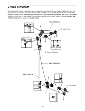
... show the correct route for each cable are labeled. Be sure that the two cables and the cable traps have not been correctly routed, the home gym system will not function properly and damage may occur. CABLE DIAGRAM The cable diagram below shows the proper routing of each cable. If the cables have been assembled correctly. Long Cable (23) 2 1-High Pulley...
... show the correct route for each cable are labeled. Be sure that the two cables and the cable traps have not been correctly routed, the home gym system will not function properly and damage may occur. CABLE DIAGRAM The cable diagram below shows the proper routing of each cable. If the cables have been assembled correctly. Long Cable (23) 2 1-High Pulley...


