Owners Manual
Page 2
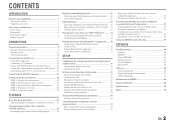
...Playing back tunes from your iPod™/iPhone 34 Connecting the Yamaha iPod universal dock 34 Controlling an iPod/iPhone 34 Playing back tunes from Bluetooth™ components....... 36 Connecting a Yamaha Bluetooth wireless audio receiver 36 Pairing Bluetooth™ components 36 Using Bluetooth™.../Setting the Advanced Setup menu 55 Setting the impedance of speakers 55 Avoiding crossing remote control signals when using multiple Yamaha receivers 56 Initializing various settings for this unit 56 Using the HDMI Control function 57 APPENDIX Troubleshooting 60 General 60 ...
...Playing back tunes from your iPod™/iPhone 34 Connecting the Yamaha iPod universal dock 34 Controlling an iPod/iPhone 34 Playing back tunes from Bluetooth™ components....... 36 Connecting a Yamaha Bluetooth wireless audio receiver 36 Pairing Bluetooth™ components 36 Using Bluetooth™.../Setting the Advanced Setup menu 55 Setting the impedance of speakers 55 Avoiding crossing remote control signals when using multiple Yamaha receivers 56 Initializing various settings for this unit 56 Using the HDMI Control function 57 APPENDIX Troubleshooting 60 General 60 ...
Owners Manual
Page 3
Sound quality control with the equalizer Speaker layout...10 - Specifying the settings for each speaker 42 - Subwoofer cable connection ...12 ■ Acoustic parameter adjustment to 5.1-channel configurations - Volume control for each speaker...43 - INTRODUCTION Features and capabilities ■ Built-in high-quality, high-power 5-channel amplifier ■ 1-button input/sound field program switching (SCENE function 26 ■ Speaker connections for speaker acoustic parameters 22 - Speaker impedance configuration...10 - Setting for 2- Speaker cable connection......
Sound quality control with the equalizer Speaker layout...10 - Specifying the settings for each speaker 42 - Subwoofer cable connection ...12 ■ Acoustic parameter adjustment to 5.1-channel configurations - Volume control for each speaker...43 - INTRODUCTION Features and capabilities ■ Built-in high-quality, high-power 5-channel amplifier ■ 1-button input/sound field program switching (SCENE function 26 ■ Speaker connections for speaker acoustic parameters 22 - Speaker impedance configuration...10 - Setting for 2- Speaker cable connection......
Owners Manual
Page 5
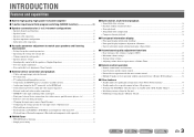
... to FM (☞p. 30). INFO MEMORY PRESET FM AM TUNING INPUT BD DVD SCENE TV CD TONE CONTROL PROGRAM RADIO STRAIGHT VIDEO AUX PORTABLE VIDEO L AUDIO R VOLUME j kl m n o p En 5 Sound effects applied during playback can also be heard through the input sources in standby mode to cycle through the headphones. J1...
... to FM (☞p. 30). INFO MEMORY PRESET FM AM TUNING INPUT BD DVD SCENE TV CD TONE CONTROL PROGRAM RADIO STRAIGHT VIDEO AUX PORTABLE VIDEO L AUDIO R VOLUME j kl m n o p En 5 Sound effects applied during playback can also be heard through the input sources in standby mode to cycle through the headphones. J1...

Owners Manual
Page 6
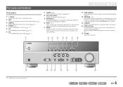
...HDMI OUT jack For connecting an HDMI - Rear panel a DOCK jack For connecting an optional Yamaha iPod universal dock (such as the AV5 or AUDIO1-2 jacks are selected (☞p. 20). g AV OUT jacks For outputting audio/video signals received when analog inputs (AV35 or AUDIO1-2) are compatible with analog...1 COAXIAL AV 2 COAXIAL (CD) AV 3 OPTICAL ( TV ) AV 4 AV 5 AV OUT AUDIO 1 AUDIO 2 AUDIO OUT SUBWOOFER Distinguishing the input and output jacks The area around the audio/video output jacks is marked in white to external devices equipped with a built-in amplifier (☞p. 12...
...HDMI OUT jack For connecting an HDMI - Rear panel a DOCK jack For connecting an optional Yamaha iPod universal dock (such as the AV5 or AUDIO1-2 jacks are selected (☞p. 20). g AV OUT jacks For outputting audio/video signals received when analog inputs (AV35 or AUDIO1-2) are compatible with analog...1 COAXIAL AV 2 COAXIAL (CD) AV 3 OPTICAL ( TV ) AV 4 AV 5 AV OUT AUDIO 1 AUDIO 2 AUDIO OUT SUBWOOFER Distinguishing the input and output jacks The area around the audio/video output jacks is marked in white to external devices equipped with a built-in amplifier (☞p. 12...
Owners Manual
Page 7
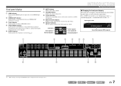
... remote control are output. En 7 j Speaker indicators Indicate speaker terminals from which signals are available for operations. Press fINFO repeatedly to cycle through an optional Yamaha iPod universal dock (such as the active input source. c Tuner indicator Lights up when the sleep timer is activated (☞p. 8). Front panel display a HDMI indicator... information display Displays a range of the input source. b CINEMA DSP indicator Lights up if corresponding cursors on menu items and settings. f MUTE indicator Flashes when audio is selected.
... remote control are output. En 7 j Speaker indicators Indicate speaker terminals from which signals are available for operations. Press fINFO repeatedly to cycle through an optional Yamaha iPod universal dock (such as the active input source. c Tuner indicator Lights up when the sleep timer is activated (☞p. 8). Front panel display a HDMI indicator... information display Displays a range of the input source. b CINEMA DSP indicator Lights up if corresponding cursors on menu items and settings. f MUTE indicator Flashes when audio is selected.

Owners Manual
Page 8
J1 DOCK A Yamaha iPod universal dock or Bluetooth wireless audio receiver connected to set the time for the sleep timer function. FM/AM tuner e Tuner keys Operates the FM/AM tuner. Selects a ... with the kExternal component operation keys without changing inputs. Sleep 60min. Remote control a b c d e f g h i j k l m SOURCE 1 1 5 TRANSMIT CODE SET SLEEP RECEIVER HDMI 2 3 4 AV 2 3 4 AUDIO 1 2 V-AUX [ A ] [ B ] DOCK TUNER FM AM PRESET TUNING INFO MEMORY MOVIE ENHANCER SUR. DECODE MUSIC STEREO STRAIGHT BD DVD SETUP SCENE TV CD RADIO OPTION ENTER...
J1 DOCK A Yamaha iPod universal dock or Bluetooth wireless audio receiver connected to set the time for the sleep timer function. FM/AM tuner e Tuner keys Operates the FM/AM tuner. Selects a ... with the kExternal component operation keys without changing inputs. Sleep 60min. Remote control a b c d e f g h i j k l m SOURCE 1 1 5 TRANSMIT CODE SET SLEEP RECEIVER HDMI 2 3 4 AV 2 3 4 AUDIO 1 2 V-AUX [ A ] [ B ] DOCK TUNER FM AM PRESET TUNING INFO MEMORY MOVIE ENHANCER SUR. DECODE MUSIC STEREO STRAIGHT BD DVD SETUP SCENE TV CD RADIO OPTION ENTER...

Owners Manual
Page 11
Surround speaker RL Front speaker R L HDMI 4 OR OUT ANTENNA FM GND AM SURROUND CENTER SPEAKERS FRONT AUDIO 2 AUDIO OUT SUBWOOFER Subwoofer Center speaker CAUTION • Remove the AC power cord of this unit. If the speaker cables short circuit, "CHECK SP WIRES!" Insert ...
Surround speaker RL Front speaker R L HDMI 4 OR OUT ANTENNA FM GND AM SURROUND CENTER SPEAKERS FRONT AUDIO 2 AUDIO OUT SUBWOOFER Subwoofer Center speaker CAUTION • Remove the AC power cord of this unit. If the speaker cables short circuit, "CHECK SP WIRES!" Insert ...
Owners Manual
Page 12
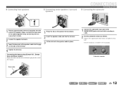
... 1 Connect the subwoofer input jack to approximately half volume (or slightly less than half). Volume: Set to the SUBWOOFER jack on this unit with an audio pin cable. 2 Set the subwoofer volume as follows. VOLUME CROSSOVER/ HIGH CUT MIN MAX MIN MAX Subwoofer examples En 12 Banana plug KERS FRONT 1 Press...
... 1 Connect the subwoofer input jack to approximately half volume (or slightly less than half). Volume: Set to the SUBWOOFER jack on this unit with an audio pin cable. 2 Set the subwoofer volume as follows. VOLUME CROSSOVER/ HIGH CUT MIN MAX MIN MAX Subwoofer examples En 12 Banana plug KERS FRONT 1 Press...
Owners Manual
Page 13
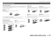
...output jacks. Use stereo pin cables, connecting the red plug to the red R jack, and the white plug to connect. ■ Audio/Video jacks HDMI jacks Digital video and digital sound are transmitted through a single jack. Connecting external devices CONNECTIONS Cable plugs and jacks The...transmits conventional analog video signals. Use a stereo mini-plug cable when connecting. Component video pin cable Video pin cable AUDIO jacks These jacks transmit conventional analog audio signals. Stereo mini-plug cable En 13 Use jacks and cables appropriate for components that you are going to the ...
...output jacks. Use stereo pin cables, connecting the red plug to the red R jack, and the white plug to connect. ■ Audio/Video jacks HDMI jacks Digital video and digital sound are transmitted through a single jack. Connecting external devices CONNECTIONS Cable plugs and jacks The...transmits conventional analog video signals. Use a stereo mini-plug cable when connecting. Component video pin cable Video pin cable AUDIO jacks These jacks transmit conventional analog audio signals. Stereo mini-plug cable En 13 Use jacks and cables appropriate for components that you are going to the ...
Owners Manual
Page 14
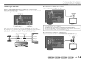
...video input COMPONENT VIDEO PR PB Y TV OPTICAL AV 1 COAXIAL AV 2 COAXIAL (CD) AV 3 OPTICAL ( TV ) AV 4 AV 5 AV OUT AUDIO 1 AUDIO 2 AUDIO OUT En 14 HDMI DOCK COMPONENT VIDEO PR ARC HDMI OUT PR (BD/DVD) HDMI 1 HDMI 2 PB PB Y MONITOR OUT Y COMPONENT VIDEO VIDEO HDMI... 3 HDMI 4 MONITOR OUT OPTICAL AV 1 COAXIAL AV 2 COAXIAL (CD) AV 3 OPTICAL ( TV ) AV 4 AV 5 AV OUT AUDIO 1 AUDIO 2 AUDIO OUT HDMI input HDMI HDMI TV COMPONENT VIDEO jacks (MONITOR OUT) VIDEO jack (MONITOR OUT) Video signals input from a particular type of jack(s) are output...
...video input COMPONENT VIDEO PR PB Y TV OPTICAL AV 1 COAXIAL AV 2 COAXIAL (CD) AV 3 OPTICAL ( TV ) AV 4 AV 5 AV OUT AUDIO 1 AUDIO 2 AUDIO OUT En 14 HDMI DOCK COMPONENT VIDEO PR ARC HDMI OUT PR (BD/DVD) HDMI 1 HDMI 2 PB PB Y MONITOR OUT Y COMPONENT VIDEO VIDEO HDMI... 3 HDMI 4 MONITOR OUT OPTICAL AV 1 COAXIAL AV 2 COAXIAL (CD) AV 3 OPTICAL ( TV ) AV 4 AV 5 AV OUT AUDIO 1 AUDIO 2 AUDIO OUT HDMI input HDMI HDMI TV COMPONENT VIDEO jacks (MONITOR OUT) VIDEO jack (MONITOR OUT) Video signals input from a particular type of jack(s) are output...

Owners Manual
Page 15
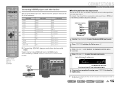
...HDMI 4 MONITOR OUT V OPTICAL AV 1 COAXIAL AV 2 COAXIAL (CD) AV 3 OPTICAL ( TV ) AV 4 AV 5 AV OUT AUDIO 1 AUDIO 2 AUDIO OUT Video input VIDEO V TV ■ Listening to TV audio To transmit sound from the TV to this unit automatically when listening to the OPTICAL jack of the AV5, AUDIO1, AUDIO2...HDMI 1 HDMI 2 PB PB Y MONITOR OUT Y COMPONENT VIDEO VIDEO HDMI 3 HDMI 4 MONITOR OUT OPTICAL COAXIAL COAXIAL (CD) OPTICAL AV OUT AUDIO OUT You can be switched automatically to match operations carried out on the TV, and that you to switch the input source to the COAXIAL...
...HDMI 4 MONITOR OUT V OPTICAL AV 1 COAXIAL AV 2 COAXIAL (CD) AV 3 OPTICAL ( TV ) AV 4 AV 5 AV OUT AUDIO 1 AUDIO 2 AUDIO OUT Video input VIDEO V TV ■ Listening to TV audio To transmit sound from the TV to this unit automatically when listening to the OPTICAL jack of the AV5, AUDIO1, AUDIO2...HDMI 1 HDMI 2 PB PB Y MONITOR OUT Y COMPONENT VIDEO VIDEO HDMI 3 HDMI 4 MONITOR OUT OPTICAL COAXIAL COAXIAL (CD) OPTICAL AV OUT AUDIO OUT You can be switched automatically to match operations carried out on the TV, and that you to switch the input source to the COAXIAL...
Owners Manual
Page 16
...HDMI 3 HDMI 4 MONITOR OUT OPTICAL COAXIAL AV 2 COAXIAL (CD) AV 3 OPTICAL ( TV ) AV 4 AV 5 AV OUT AUDIO 1 AUDIO 2 AUDIO OUT 1 Use the dInput selector to select the desired HDMI input source. 2 Press qOPTION to close the Option menu. J1 3 Press jCursor C... OUT OPTICAL AV 1 COAXIAL AV 2 COAXIAL (CD) AV 3 OPTICAL ( TV ) AV 4 AV 5 AV OUT AUDIO 1 AUDIO 2 AUDIO OUT BD/DVD player CONNECTIONS Connecting external devices ■ Receiving audio from other audio input sources. J 1 : See the section on the external components. SOURCE 1 1 5 TRANSMIT CODE SET SLEEP RECEIVER...
...HDMI 3 HDMI 4 MONITOR OUT OPTICAL COAXIAL AV 2 COAXIAL (CD) AV 3 OPTICAL ( TV ) AV 4 AV 5 AV OUT AUDIO 1 AUDIO 2 AUDIO OUT 1 Use the dInput selector to select the desired HDMI input source. 2 Press qOPTION to close the Option menu. J1 3 Press jCursor C... OUT OPTICAL AV 1 COAXIAL AV 2 COAXIAL (CD) AV 3 OPTICAL ( TV ) AV 4 AV 5 AV OUT AUDIO 1 AUDIO 2 AUDIO OUT BD/DVD player CONNECTIONS Connecting external devices ■ Receiving audio from other audio input sources. J 1 : See the section on the external components. SOURCE 1 1 5 TRANSMIT CODE SET SLEEP RECEIVER...

Owners Manual
Page 17
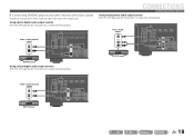
... 1 COAXIAL AV 2 COAXIAL (CD) AV 3 OPTICAL ( TV ) AV 4 AV 5 AV OUT AUDIO 1 AUDIO 2 AUDIO OUT CONNECTIONS Connecting external devices ■ Component connections to for playback. Using optical digital audio output sources Select the AV1 input that the external device is connected by component video cable to for...L CR SL SR En 17 Select the AV input source (AV1-2) that the external device is connected to analog audio output devices Component video / Audio output COMPONENT VIDEO PR PB Y AUDIO L R DOCK COMPONENT VIDEO PR ARC HDMI OUT PR PR (BD/DVD) HDMI 1 HDMI 2 PB PB ...
... 1 COAXIAL AV 2 COAXIAL (CD) AV 3 OPTICAL ( TV ) AV 4 AV 5 AV OUT AUDIO 1 AUDIO 2 AUDIO OUT CONNECTIONS Connecting external devices ■ Component connections to for playback. Using optical digital audio output sources Select the AV1 input that the external device is connected by component video cable to for...L CR SL SR En 17 Select the AV input source (AV1-2) that the external device is connected to analog audio output devices Component video / Audio output COMPONENT VIDEO PR PB Y AUDIO L R DOCK COMPONENT VIDEO PR ARC HDMI OUT PR PR (BD/DVD) HDMI 1 HDMI 2 PB PB ...
Owners Manual
Page 18
... AV 3 R OPTICAL ( TV ) AV 4 AV 5 AV OUT AUDIO 1 AUDIO 2 AUDIO OUT O O OPTICAL AV 1 COAXIAL AV 2 COAXIAL (CD) AV 3 OPTICAL TV AV 5 AV OUT AUDIO 1 AUDIO 2 AUDIO OUT BD/DVD player Using coaxial digital audio output sources Select the AV3 input that the external device is connected to ...VIDEO VIDEO HDMI 3 HDMI 4 MONITOR OUT C OPTICAL COAXIAL AV 1 AV 2 COAXIAL (CD) OPTICAL ( TV ) AV 4 AV 5 AV OUT AUDIO 1 AUDIO 2 AUDIO OUT En 18 Video / Audio (Optical) output VIDEO V OPTICAL DOCK COMPONENT VIDEO PR ARC HDMI OUT PR (BD/DVD) HDMI 1 HDMI 2 PB Y MONITOR OUT PB Y ...
... AV 3 R OPTICAL ( TV ) AV 4 AV 5 AV OUT AUDIO 1 AUDIO 2 AUDIO OUT O O OPTICAL AV 1 COAXIAL AV 2 COAXIAL (CD) AV 3 OPTICAL TV AV 5 AV OUT AUDIO 1 AUDIO 2 AUDIO OUT BD/DVD player Using coaxial digital audio output sources Select the AV3 input that the external device is connected to ...VIDEO VIDEO HDMI 3 HDMI 4 MONITOR OUT C OPTICAL COAXIAL AV 1 AV 2 COAXIAL (CD) OPTICAL ( TV ) AV 4 AV 5 AV OUT AUDIO 1 AUDIO 2 AUDIO OUT En 18 Video / Audio (Optical) output VIDEO V OPTICAL DOCK COMPONENT VIDEO PR ARC HDMI OUT PR (BD/DVD) HDMI 1 HDMI 2 PB Y MONITOR OUT PB Y ...
Owners Manual
Page 19
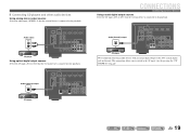
...C HDMI 3 HDMI 4 MONITOR OUT OPTICAL AV 1 COAXIAL COAXIAL (CD) OPTICAL ( TV ) AV 4 AV 5 AV OUT AUDIO 1 AUDIO 2 AUDIO OUT CD player We recommend connecting audio devices with an coaxial digital output to the AV input 3 just by pressing the "CD" SCENE key (☞p. 26). This ...Y COMPONENT VIDEO VIDEO HDMI 3 HDMI 4 MONITOR OUT OPTICAL COAXIAL AV 2 COAXIAL (CD) AV 3 OPTICAL TV AV 5 AV OUT AUDIO 1 AUDIO 2 AUDIO OUT CONNECTIONS Connecting external devices Using coaxial digital output sources Select the AV input (AV2 or AV3) that the external device is connected to ...
...C HDMI 3 HDMI 4 MONITOR OUT OPTICAL AV 1 COAXIAL COAXIAL (CD) OPTICAL ( TV ) AV 4 AV 5 AV OUT AUDIO 1 AUDIO 2 AUDIO OUT CD player We recommend connecting audio devices with an coaxial digital output to the AV input 3 just by pressing the "CD" SCENE key (☞p. 26). This ...Y COMPONENT VIDEO VIDEO HDMI 3 HDMI 4 MONITOR OUT OPTICAL COAXIAL AV 2 COAXIAL (CD) AV 3 OPTICAL TV AV 5 AV OUT AUDIO 1 AUDIO 2 AUDIO OUT CONNECTIONS Connecting external devices Using coaxial digital output sources Select the AV input (AV2 or AV3) that the external device is connected to ...
Owners Manual
Page 20
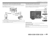
...AUX input to the external device's video input jack and analog audio input jacks. AUDIO OUT RADIO STRAIGHT VIDEO AUX PORTABLE VIDEO L AUDIO R VL R Audio output L Audio output R V Video output AUDIO VIDEO Portable audio player Video cameras • Be sure to turn down the ... OUT L L R R OPTICAL AV 1 COAXIAL AV 2 COAXIAL (CD) AV 3 OPTICAL ( TV ) AV 4 AV 5 AV OUT AUDIO 1 AUDIO 2 AUDIO OUT VCR Audio input AUDIO L R Audio recorder Using the AV OUT jacks Connect this unit and the other devices. • When external components are connected to other TVs or external...
...AUX input to the external device's video input jack and analog audio input jacks. AUDIO OUT RADIO STRAIGHT VIDEO AUX PORTABLE VIDEO L AUDIO R VL R Audio output L Audio output R V Video output AUDIO VIDEO Portable audio player Video cameras • Be sure to turn down the ... OUT L L R R OPTICAL AV 1 COAXIAL AV 2 COAXIAL (CD) AV 3 OPTICAL ( TV ) AV 4 AV 5 AV OUT AUDIO 1 AUDIO 2 AUDIO OUT VCR Audio input AUDIO L R Audio recorder Using the AV OUT jacks Connect this unit and the other devices. • When external components are connected to other TVs or external...
Owners Manual
Page 22
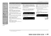
... listening point so that the sound is 16 cm or smaller - Carry out the following speaker configuration: - SOURCE 1 1 5 TRANSMIT CODE SET SLEEP RECEIVER HDMI 2 3 4 AV 2 3 4 AUDIO 1 2 V-AUX [ A ] [ B ] DOCK TUNER FM AM PRESET TUNING INFO MEMORY MOVIE ENHANCER SUR. CONFIG VOL.
... listening point so that the sound is 16 cm or smaller - Carry out the following speaker configuration: - SOURCE 1 1 5 TRANSMIT CODE SET SLEEP RECEIVER HDMI 2 3 4 AV 2 3 4 AUDIO 1 2 V-AUX [ A ] [ B ] DOCK TUNER FM AM PRESET TUNING INFO MEMORY MOVIE ENHANCER SUR. CONFIG VOL.
Owners Manual
Page 23
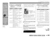
... if you configured are produced from the subwoofer (or from the front speakers if there is optional. None/Small/ Large Crossover Audio with a frequency below this limit will be output from the listening point 7 Press jCursor C to the previous menu. Woofer ...;;;;;;feet SW L CR SL SR 9 Press jRETURN when setting is complete. SOURCE 1 1 5 TRANSMIT CODE SET SLEEP RECEIVER HDMI 2 3 4 AV 2 3 4 AUDIO 1 2 V-AUX [ A ] [ B ] DOCK TUNER FM AM PRESET TUNING INFO MEMORY MOVIE ENHANCER SUR. Information Description Setting Unit Switches between setting feet (ft)...
... if you configured are produced from the subwoofer (or from the front speakers if there is optional. None/Small/ Large Crossover Audio with a frequency below this limit will be output from the listening point 7 Press jCursor C to the previous menu. Woofer ...;;;;;;feet SW L CR SL SR 9 Press jRETURN when setting is complete. SOURCE 1 1 5 TRANSMIT CODE SET SLEEP RECEIVER HDMI 2 3 4 AV 2 3 4 AUDIO 1 2 V-AUX [ A ] [ B ] DOCK TUNER FM AM PRESET TUNING INFO MEMORY MOVIE ENHANCER SUR. Information Description Setting Unit Switches between setting feet (ft)...
Owners Manual
Page 24
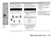
... >Off On VOL. To raise the volume: Press jCursor E. Return to display "Test Tone" and press jENTER. SOURCE 1 1 5 TRANSMIT CODE SET SLEEP RECEIVER HDMI 2 3 4 AV 2 3 4 AUDIO 1 2 V-AUX [ A ] [ B ] DOCK TUNER FM AM PRESET TUNING INFO MEMORY MOVIE ENHANCER SUR. DECODE MUSIC STEREO STRAIGHT BD DVD SETUP SCENE TV CD RADIO OPTION STEP...
... >Off On VOL. To raise the volume: Press jCursor E. Return to display "Test Tone" and press jENTER. SOURCE 1 1 5 TRANSMIT CODE SET SLEEP RECEIVER HDMI 2 3 4 AV 2 3 4 AUDIO 1 2 V-AUX [ A ] [ B ] DOCK TUNER FM AM PRESET TUNING INFO MEMORY MOVIE ENHANCER SUR. DECODE MUSIC STEREO STRAIGHT BD DVD SETUP SCENE TV CD RADIO OPTION STEP...

Owners Manual
Page 25
... components (TV, DVD d player, etc.) connected to obtain desired tone. PLAYBACK SOURCE 1 1 5 TRANSMIT CODE SET SLEEP RECEIVER HDMI 2 3 4 AV 2 3 4 AUDIO 1 2 V-AUX [ A ] [ B ] DOCK TUNER FM AM PRESET TUNING INFO MEMORY MOVIE ENHANCER SUR. Set the headphone tone control with the r external component for... a few seconds. SW 0.0dB L C R SL SR 2 Press PROGRAM l / h to mute the audio output. J1 3 Play the external component that you set separately. J 1 : You can be set the balance extremely off, sounds may not ...
... components (TV, DVD d player, etc.) connected to obtain desired tone. PLAYBACK SOURCE 1 1 5 TRANSMIT CODE SET SLEEP RECEIVER HDMI 2 3 4 AV 2 3 4 AUDIO 1 2 V-AUX [ A ] [ B ] DOCK TUNER FM AM PRESET TUNING INFO MEMORY MOVIE ENHANCER SUR. Set the headphone tone control with the r external component for... a few seconds. SW 0.0dB L C R SL SR 2 Press PROGRAM l / h to mute the audio output. J1 3 Play the external component that you set separately. J 1 : You can be set the balance extremely off, sounds may not ...


