
Quick Reference Guide
Page 61
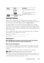
... error, beep codes, or diagnostics light patterns, record your computer. Quick Reference Guide 61 unjumpered Solving Problems Dell provides a number of the procedures in this section and run the Dell Diagnostics before you want to help from Dell, write a detailed description of the Express Service Code and Service Tag, see "Entering System Setup" in...
... error, beep codes, or diagnostics light patterns, record your computer. Quick Reference Guide 61 unjumpered Solving Problems Dell provides a number of the procedures in this section and run the Dell Diagnostics before you want to help from Dell, write a detailed description of the Express Service Code and Service Tag, see "Entering System Setup" in...
Quick Reference Guide
Page 63
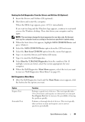
...and requires no interaction on page 63). This test typically takes 10 to start the Dell Diagnostics. 8 Select Run the 32 Bit Dell Diagnostics from the numbered list. Dell Diagnostics Main Menu 1 After the Dell Diagnostics loads and the Main Menu screen appears, click the button for one time only.... This test typically takes an hour or more and requires you see "Dell Diagnostics Main Menu" on ...
...and requires no interaction on page 63). This test typically takes 10 to start the Dell Diagnostics. 8 Select Run the 32 Bit Dell Diagnostics from the numbered list. Dell Diagnostics Main Menu 1 After the Dell Diagnostics loads and the Main Menu screen appears, click the button for one time only.... This test typically takes an hour or more and requires you see "Dell Diagnostics Main Menu" on ...
User's Guide
Page 53
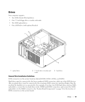
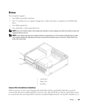
... media card reader 3 hard drive General Drive Installation Guidelines SATA connectors on the system board.) Drives 53 Hard drives must be connected to the lower numbered SATA connectors, while any other SATA devices (like an optical drive) must be connected to the remaining SATA connectors... numbered higher than the one SATA optical drive, connect the two hard drives to the SATA0 and SATA1 connectors, and connect the SATA optical drive to . ...
... media card reader 3 hard drive General Drive Installation Guidelines SATA connectors on the system board.) Drives 53 Hard drives must be connected to the lower numbered SATA connectors, while any other SATA devices (like an optical drive) must be connected to the remaining SATA connectors... numbered higher than the one SATA optical drive, connect the two hard drives to the SATA0 and SATA1 connectors, and connect the SATA optical drive to . ...
User's Guide
Page 72
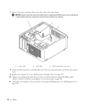
See "System Setup" on page 280. 11 Verify that is labeled with a number higher than those connected to any hard drives installed in the computer. 1 2 3 1 power cable 2 data cable 3 SATA optical drive connector 8 Check all cable connections, and ... out of the way to provide airflow for the fan and cooling vents. 9 Replace the computer cover (see "Dell Diagnostics" on page 317). 10 Update your configuration information in system setup by running the Dell Diagnostics (see "Replacing the Computer Cover" on page 353). 72 Drives NOTICE: Always connect the optical drive...
See "System Setup" on page 280. 11 Verify that is labeled with a number higher than those connected to any hard drives installed in the computer. 1 2 3 1 power cable 2 data cable 3 SATA optical drive connector 8 Check all cable connections, and ... out of the way to provide airflow for the fan and cooling vents. 9 Replace the computer cover (see "Dell Diagnostics" on page 317). 10 Update your configuration information in system setup by running the Dell Diagnostics (see "Replacing the Computer Cover" on page 353). 72 Drives NOTICE: Always connect the optical drive...
User's Guide
Page 81
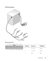
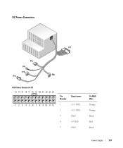
DC Power Connectors DC Power Connector P1 13 14 15 16 17 18 19 20 21 22 23 24 1 2 3 4 5 6 7 8 9 10 11 12 Pin Number 1 2 3 Signal name +3.3 VDC +3.3 VDC GND 18-AWG Wire Orange Orange Black Power Supply 81
DC Power Connectors DC Power Connector P1 13 14 15 16 17 18 19 20 21 22 23 24 1 2 3 4 5 6 7 8 9 10 11 12 Pin Number 1 2 3 Signal name +3.3 VDC +3.3 VDC GND 18-AWG Wire Orange Orange Black Power Supply 81
User's Guide
Page 82
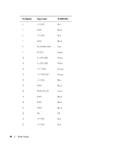
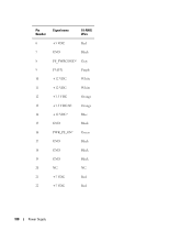
Pin Number 4 5 6 7 8 9 10 11 12 13 14 15 16 17 18 19 20 21 22 Signal name +5 VDC GND +5 VDC GND PS_PWRGOOD P5AUX V_12P0_DIG V_12P0_DIG +3.3 VDC +3.3VDC/SE* -12 VDC GND PWR_PS_ON GND GND GND NC +5 VDC +5 VDC 18-AWG Wire Red Black Red Black Gray Purple White White Orange Orange Blue Black Green Black Black Black NC Red Red 82 Power Supply
Pin Number 4 5 6 7 8 9 10 11 12 13 14 15 16 17 18 19 20 21 22 Signal name +5 VDC GND +5 VDC GND PS_PWRGOOD P5AUX V_12P0_DIG V_12P0_DIG +3.3 VDC +3.3VDC/SE* -12 VDC GND PWR_PS_ON GND GND GND NC +5 VDC +5 VDC 18-AWG Wire Red Black Red Black Gray Purple White White Orange Orange Blue Black Green Black Black Black NC Red Red 82 Power Supply
User's Guide
Page 83
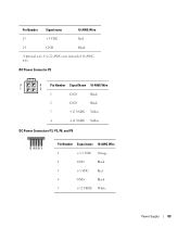
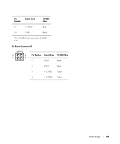
Pin Number Signal name 18-AWG Wire 23 +5 VDC Red 24 GND Black *Optional wire. Use 22-AWG wire instead of 18-AWG wire. DC Power Connector P2 3 4 Pin Number Signal Name 18-AWG Wire 1 2 1 GND Black 2 GND Black 3 +12 VADC Yellow 4 +12 VADC Yellow DC Power Connectors P3, P5, P8, and P9 Pin Number Signal name 18-AWG Wire 1 +3.3 VDC Orange 2 GND Black 3 +5 VDC Red 4 GND Black 5 +12 VBDC White Power Supply 83
Pin Number Signal name 18-AWG Wire 23 +5 VDC Red 24 GND Black *Optional wire. Use 22-AWG wire instead of 18-AWG wire. DC Power Connector P2 3 4 Pin Number Signal Name 18-AWG Wire 1 2 1 GND Black 2 GND Black 3 +12 VADC Yellow 4 +12 VADC Yellow DC Power Connectors P3, P5, P8, and P9 Pin Number Signal name 18-AWG Wire 1 +3.3 VDC Orange 2 GND Black 3 +5 VDC Red 4 GND Black 5 +12 VBDC White Power Supply 83
User's Guide
Page 84
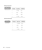
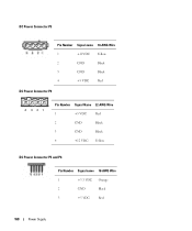
DC Power Connector P7 4 321 Pin Number Signal Name 22-AWG Wire 1 +5 VDC Red 2 GND Black 3 GND Black 4 +12 VDC Yellow DC Power Connector P10 Pin Number Signal name 18-AWG Wire 1 +12 VBDC White 2 GND Black 3 GND Black 4 +5 VDC Red 84 Power Supply
DC Power Connector P7 4 321 Pin Number Signal Name 22-AWG Wire 1 +5 VDC Red 2 GND Black 3 GND Black 4 +12 VDC Yellow DC Power Connector P10 Pin Number Signal name 18-AWG Wire 1 +12 VBDC White 2 GND Black 3 GND Black 4 +5 VDC Red 84 Power Supply
User's Guide
Page 127
... second SATA hard drive) • One SATA optical drive • One eSATA drive (with optional bracket) NOTE: Due to the limited number of the drive. Any other SATA device (like an optical drive) must be installed in place of drive bays and controllers on the system... 3.5-inch device (floppy drive or media card reader) installed, the appropriate drive bay insert must be connected to connect all supported devices at once. Contact Dell if you need a drive bay insert. 1 2 3 1 optical drive 2 floppy drive 3 hard drive General Drive Installation Guidelines SATA connectors on this ...
... second SATA hard drive) • One SATA optical drive • One eSATA drive (with optional bracket) NOTE: Due to the limited number of the drive. Any other SATA device (like an optical drive) must be installed in place of drive bays and controllers on the system... 3.5-inch device (floppy drive or media card reader) installed, the appropriate drive bay insert must be connected to connect all supported devices at once. Contact Dell if you need a drive bay insert. 1 2 3 1 optical drive 2 floppy drive 3 hard drive General Drive Installation Guidelines SATA connectors on this ...
User's Guide
Page 137
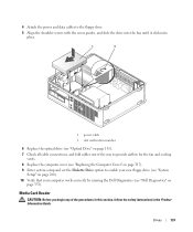
... Drive option to enable your new floppy drive (see "System Setup" on page 280). 10 Verify that your computer works correctly by running the Dell Diagnostics (see "Dell Diagnostics" on page 131). 7 Check all cable connections, and fold cables out of the procedures in this section, follow the safety instructions in the... drive. 5 Align the shoulder screws with the screw guides, and slide the drive into the bay until it clicks into place. 1 2 1 power cable 2 slot verification number 6 Replace the optical drive (see "Optical Drive" on page 353).
... Drive option to enable your new floppy drive (see "System Setup" on page 280). 10 Verify that your computer works correctly by running the Dell Diagnostics (see "Dell Diagnostics" on page 131). 7 Check all cable connections, and fold cables out of the procedures in this section, follow the safety instructions in the... drive. 5 Align the shoulder screws with the screw guides, and slide the drive into the bay until it clicks into place. 1 2 1 power cable 2 slot verification number 6 Replace the optical drive (see "Optical Drive" on page 353).
User's Guide
Page 141
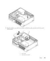
5 Align the shoulder screws with the screw guides, and slide the media card reader into the bay until it clicks into place. 1 power cable 2 slot verification number Drives 141
5 Align the shoulder screws with the screw guides, and slide the media card reader into the bay until it clicks into place. 1 power cable 2 slot verification number Drives 141
User's Guide
Page 145
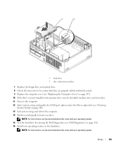
1 2 1 hard drive 2 slot verification number 7 Replace the floppy drive and optical drive. 8 Check all connectors to be certain ...on the computer. 12 Enter system setup, and update the SATA port option under the Drives option list (see "Dell Diagnostics" on page 353). 16 Install your operating system on page 280). 13 Exit system setup, and reboot ..., see the documentation that came with your operating system. 15 Test the hard drive by running the Dell Diagnostics (see "Entering System Setup" on the hard drive. Drives 145 NOTE: For instructions, see the documentation that ...
1 2 1 hard drive 2 slot verification number 7 Replace the floppy drive and optical drive. 8 Check all connectors to be certain ...on the computer. 12 Enter system setup, and update the SATA port option under the Drives option list (see "Dell Diagnostics" on page 353). 16 Install your operating system on page 280). 13 Exit system setup, and reboot ..., see the documentation that came with your operating system. 15 Test the hard drive by running the Dell Diagnostics (see "Entering System Setup" on the hard drive. Drives 145 NOTE: For instructions, see the documentation that ...
User's Guide
Page 157
DC Power Connectors DC Power Connector P1 13 14 15 16 17 18 19 20 21 22 23 24 1 2 3 4 5 6 7 8 9 10 11 12 Pin Number Signal name 1 +3.3 VDC 2 +3.3 VDC 3 GND 4 +5 VDC 5 GND 18-AWG Wire Orange Orange Black Red Black Power Supply 157
DC Power Connectors DC Power Connector P1 13 14 15 16 17 18 19 20 21 22 23 24 1 2 3 4 5 6 7 8 9 10 11 12 Pin Number Signal name 1 +3.3 VDC 2 +3.3 VDC 3 GND 4 +5 VDC 5 GND 18-AWG Wire Orange Orange Black Red Black Power Supply 157
User's Guide
Page 158
Pin Number Signal name 18-AWG Wire 6 +5 VDC Red 7 GND Black 8 PS_PWRGOOD* Gray 9 P5AUX Purple 10 +12 VDC White 11 +12 VDC White 12 +3.3 VDC Orange 13 +3.3 VDC/SE Orange 14 +12 VDC* Blue 15 GND Black 16 PWR_PS_ON* Green 17 GND Black 18 GND Black 19 GND Black 20 NC NC 21 +5 VDC Red 22 +5 VDC Red 158 Power Supply
Pin Number Signal name 18-AWG Wire 6 +5 VDC Red 7 GND Black 8 PS_PWRGOOD* Gray 9 P5AUX Purple 10 +12 VDC White 11 +12 VDC White 12 +3.3 VDC Orange 13 +3.3 VDC/SE Orange 14 +12 VDC* Blue 15 GND Black 16 PWR_PS_ON* Green 17 GND Black 18 GND Black 19 GND Black 20 NC NC 21 +5 VDC Red 22 +5 VDC Red 158 Power Supply
User's Guide
Page 159
DC Power Connector P2 3 4 Pin Number Signal Name 18-AWG Wire 1 2 1 GND Black 2 GND Black 3 +12 VDC Yellow 4 +12 VDC Yellow Power Supply 159 Pin Number Signal name 18-AWG Wire 23 +5 VDC 24 GND Red Black *Use 22-AWG wire instead of 18-AWG wire.
DC Power Connector P2 3 4 Pin Number Signal Name 18-AWG Wire 1 2 1 GND Black 2 GND Black 3 +12 VDC Yellow 4 +12 VDC Yellow Power Supply 159 Pin Number Signal name 18-AWG Wire 23 +5 VDC 24 GND Red Black *Use 22-AWG wire instead of 18-AWG wire.
User's Guide
Page 160
DC Power Connector P3 Pin Number Signal name 18-AWG Wire 1 +12VDC Yellow 2 GND Black 3 GND Black 4 +5 VDC Red DC Power Connector P4 4 321 Pin Number Signal Name 22-AWG Wire 1 +5 VDC Red 2 GND Black 3 GND Black 4 +12 VDC Yellow DC Power Connector P5 and P6 Pin Number Signal name 18-AWG Wire 1 +3.3 VDC Orange 2 GND Black 3 +5 VDC Red 160 Power Supply
DC Power Connector P3 Pin Number Signal name 18-AWG Wire 1 +12VDC Yellow 2 GND Black 3 GND Black 4 +5 VDC Red DC Power Connector P4 4 321 Pin Number Signal Name 22-AWG Wire 1 +5 VDC Red 2 GND Black 3 GND Black 4 +12 VDC Yellow DC Power Connector P5 and P6 Pin Number Signal name 18-AWG Wire 1 +3.3 VDC Orange 2 GND Black 3 +5 VDC Red 160 Power Supply
User's Guide
Page 221
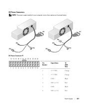
DC Power Connectors NOTE: The power supply installed in your computer is one of two options as illustrated below. DC Power Connector P1 13 14 15 16 17 18 19 20 21 22 23 24 1 2 3 4 5 6 7 8 9 10 11 12 Pin Number Signal Name 1 +3.3 VDC 2 +3.3 VDC 3 GND 4 VCC (+5 V) 5 GND 6 VCC (+5 V) 18AWG Wire Orange Orange Black Red Black Red Power Supply 221
DC Power Connectors NOTE: The power supply installed in your computer is one of two options as illustrated below. DC Power Connector P1 13 14 15 16 17 18 19 20 21 22 23 24 1 2 3 4 5 6 7 8 9 10 11 12 Pin Number Signal Name 1 +3.3 VDC 2 +3.3 VDC 3 GND 4 VCC (+5 V) 5 GND 6 VCC (+5 V) 18AWG Wire Orange Orange Black Red Black Red Power Supply 221

User's Guide
Page 222
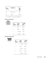
Pin Number Signal Name 18AWG Wire 7 GND Black 8 PS_PWRGOOD* Gray 9 P5AUX Purple 10 V_12P0_DIG Yellow 11 V_12P0_DIG Yellow 12 +3.3 V Orange 13 +3.3V (optional) Orange 14 -12 V* Blue 15 GND Black 16 PWR_PS_ON Green 17 GND Black 18 GND Black 19 GND Black 20 NC NC 21 VCC (+5V) Red 22 VCC (+5V) Red 222 Power Supply
Pin Number Signal Name 18AWG Wire 7 GND Black 8 PS_PWRGOOD* Gray 9 P5AUX Purple 10 V_12P0_DIG Yellow 11 V_12P0_DIG Yellow 12 +3.3 V Orange 13 +3.3V (optional) Orange 14 -12 V* Blue 15 GND Black 16 PWR_PS_ON Green 17 GND Black 18 GND Black 19 GND Black 20 NC NC 21 VCC (+5V) Red 22 VCC (+5V) Red 222 Power Supply
User's Guide
Page 223
Pin Number Signal Name 18AWG Wire 23 VCC (+5V) Red 24 GND Black *Use 22-AWG wire instead of 18-AWG wire. DC Power Connector P2 3 4 1 2 Pin Signal 18-AWG Number Name Wire 1 GND Black 2 GND Black 3 +12 VDC Yellow 4 +12 VDC Yellow DC Power Connectors P3 Pin Number Signal Name 18-AWG Wire 1 +3.3 VDC Orange 2 GND Black 3 +5 VDC Red 4 GND Black 5 +12 VDC Yellow Power Supply 223
Pin Number Signal Name 18AWG Wire 23 VCC (+5V) Red 24 GND Black *Use 22-AWG wire instead of 18-AWG wire. DC Power Connector P2 3 4 1 2 Pin Signal 18-AWG Number Name Wire 1 GND Black 2 GND Black 3 +12 VDC Yellow 4 +12 VDC Yellow DC Power Connectors P3 Pin Number Signal Name 18-AWG Wire 1 +3.3 VDC Orange 2 GND Black 3 +5 VDC Red 4 GND Black 5 +12 VDC Yellow Power Supply 223
User's Guide
Page 224
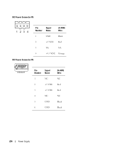
DC Power Connector P5 Pin Signal Number Name 24-AWG Wire 1 GND Black 2 +5 VDC Red 3 NA NA 4 +3.3 VDC Orange DC Power Connector P6 6 5 4 3 2 1 Pin Signal Number Name 1 NC 2 +5 VDC 3 +5 VDC 4 NC 5 GND 6 GND 24-AWG Wire NC Red Red NC Black Black 224 Power Supply
DC Power Connector P5 Pin Signal Number Name 24-AWG Wire 1 GND Black 2 +5 VDC Red 3 NA NA 4 +3.3 VDC Orange DC Power Connector P6 6 5 4 3 2 1 Pin Signal Number Name 1 NC 2 +5 VDC 3 +5 VDC 4 NC 5 GND 6 GND 24-AWG Wire NC Red Red NC Black Black 224 Power Supply


