
Quick Reference Guide
Page 3
... Jumper Settings 26 Desktop Computer 27 System Views 27 Removing the Computer Cover 32 Inside Your Computer 33 System Board Components 35 Jumper Settings 36 Small Form Factor Computer 37 System Views 37 Removing the Computer Cover 43 Contents 3
... Jumper Settings 26 Desktop Computer 27 System Views 27 Removing the Computer Cover 32 Inside Your Computer 33 System Board Components 35 Jumper Settings 36 Small Form Factor Computer 37 System Views 37 Removing the Computer Cover 43 Contents 3
Quick Reference Guide
Page 4
...Board Components 46 Jumper Settings 47 Ultra Small Form Factor Computer 48 System Views 48 Removing the Computer Cover 55 Inside Your Computer 56 Cable Cover (Optional 57 System Board Components 59 Jumper Settings 60 Solving Problems 61 Dell Diagnostics 61 System Lights 65 Diagnostic Lights ... and Hardware Incompatibilities 72 Restoring Your Operating System 73 Using Microsoft Windows System Restore . . . . 73 Using Dell™ PC Restore and Dell Factory Image Restore 75 Using the Drivers and Utilities Media 78 Reinstalling Drivers and Utilities 79 Index 83 4 Contents
...Board Components 46 Jumper Settings 47 Ultra Small Form Factor Computer 48 System Views 48 Removing the Computer Cover 55 Inside Your Computer 56 Cable Cover (Optional 57 System Board Components 59 Jumper Settings 60 Solving Problems 61 Dell Diagnostics 61 System Lights 65 Diagnostic Lights ... and Hardware Incompatibilities 72 Restoring Your Operating System 73 Using Microsoft Windows System Restore . . . . 73 Using Dell™ PC Restore and Dell Factory Image Restore 75 Using the Drivers and Utilities Media 78 Reinstalling Drivers and Utilities 79 Index 83 4 Contents
Quick Reference Guide
Page 15
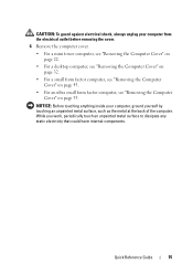
... Cover" on page 22. • For a desktop computer, see "Removing the Computer Cover" on page 32. • For a small form factor computer, see "Removing the Computer Cover" on page 43. • For an ultra small form factor computer, see "Removing the Computer Cover" on page 55. While you work, periodically touch an unpainted metal surface to...
... Cover" on page 22. • For a desktop computer, see "Removing the Computer Cover" on page 32. • For a small form factor computer, see "Removing the Computer Cover" on page 43. • For an ultra small form factor computer, see "Removing the Computer Cover" on page 55. While you work, periodically touch an unpainted metal surface to...

Quick Reference Guide
Page 37
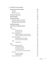
Quick Reference Guide 37 It is being reset (jumpered temporarily). Jumper RTCRST Setting jumpered Description The real-time clock has not been reset. unjumpered Small Form Factor Computer System Views Front View 1 2 3 4 5 6 11 10 1 USB 2.0 connectors (2) 98 7 Use the front USB connectors for devices that typically remain connected, such as joysticks or ...
Quick Reference Guide 37 It is being reset (jumpered temporarily). Jumper RTCRST Setting jumpered Description The real-time clock has not been reset. unjumpered Small Form Factor Computer System Views Front View 1 2 3 4 5 6 11 10 1 USB 2.0 connectors (2) 98 7 Use the front USB connectors for devices that typically remain connected, such as joysticks or ...

Quick Reference Guide
Page 48
... to prevent the cables from being reset (jumpered temporarily). Front View 1 23 4 5 9 8 7 6 48 Quick Reference Guide To order this bracket, contact Dell (see "Contacting Dell" in the User's Guide). unjumpered Ultra Small Form Factor Computer System Views NOTICE: Do not place your computer under a desk top or on . Jumper RTCRST Setting jumpered Description The real...
... to prevent the cables from being reset (jumpered temporarily). Front View 1 23 4 5 9 8 7 6 48 Quick Reference Guide To order this bracket, contact Dell (see "Contacting Dell" in the User's Guide). unjumpered Ultra Small Form Factor Computer System Views NOTICE: Do not place your computer under a desk top or on . Jumper RTCRST Setting jumpered Description The real...
User's Guide
Page 7
... Intrusion Switch 170 Removing the Chassis Intrusion Switch 170 Replacing the Chassis Intrusion Switch 171 Resetting the Chassis Intrusion Detector 171 System Board Components 172 Small Form Factor Computer Specifications 175 Cards 181 PCI Cards 181 Installing a PCI Card 181 Removing a PCI Card 184 PCI Express and DVI Cards 185 Installing a PCI Express...
... Intrusion Switch 170 Removing the Chassis Intrusion Switch 170 Replacing the Chassis Intrusion Switch 171 Resetting the Chassis Intrusion Detector 171 System Board Components 172 Small Form Factor Computer Specifications 175 Cards 181 PCI Cards 181 Installing a PCI Card 181 Removing a PCI Card 184 PCI Express and DVI Cards 185 Installing a PCI Express...
User's Guide
Page 9
... Board Components 236 Cable Cover (Optional 237 Attaching the Cable Cover 237 Removing the Cable Cover 237 Connecting the AC Power Adapter 238 Dell Badge 239 Ultra Small Form Factor Computer Specifications 241 Drives 247 General Installation Guidelines 247 Connecting Drive Cables 247 Data Interface Connectors 247 Power Cable Connectors 248 Connecting and Disconnecting...
... Board Components 236 Cable Cover (Optional 237 Attaching the Cable Cover 237 Removing the Cable Cover 237 Connecting the AC Power Adapter 238 Dell Badge 239 Ultra Small Form Factor Computer Specifications 241 Drives 247 General Installation Guidelines 247 Connecting Drive Cables 247 Data Interface Connectors 247 Power Cable Connectors 248 Connecting and Disconnecting...
User's Guide
Page 12
... Board Removing the System Board: Mini Tower, Desktop, Small Form Factor, and Ultra Small Form Factor Computers 307 Mini Tower System Board Screws 308 Desktop System Board Screws 309 Small Form Factor System Board Screws 310 Ultra Small Form Factor System Board Screws 311 Replacing the System Board: Mini Tower, Desktop, Small Form Factor, and Ultra Small Form Factor Computers 311 12 Memory DDR2 Memory Overview 313 Addressing...
... Board Removing the System Board: Mini Tower, Desktop, Small Form Factor, and Ultra Small Form Factor Computers 307 Mini Tower System Board Screws 308 Desktop System Board Screws 309 Small Form Factor System Board Screws 310 Ultra Small Form Factor System Board Screws 311 Replacing the System Board: Mini Tower, Desktop, Small Form Factor, and Ultra Small Form Factor Computers 311 12 Memory DDR2 Memory Overview 313 Addressing...
User's Guide
Page 22
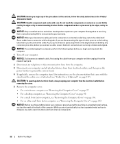
... "Removing the Computer Cover" on a card. Do not touch the components or contacts on page 168. • For an ultra small form factor computer, see the documentation that is not authorized by Dell is not covered by touching an unpainted metal surface, such as a processor by its edges, not by its strain-relief loop...
... "Removing the Computer Cover" on a card. Do not touch the components or contacts on page 168. • For an ultra small form factor computer, see the documentation that is not authorized by Dell is not covered by touching an unpainted metal surface, such as a processor by its edges, not by its strain-relief loop...
User's Guide
Page 29
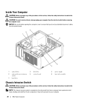
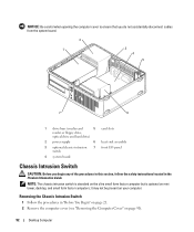
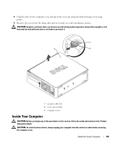
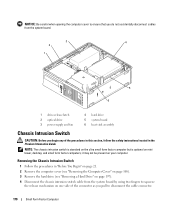
NOTE: The chassis intrusion switch is standard on the ultra small form factor computer but is optional on your computer from the system board. 3 2 1 4 5 6 7 1 optical drive 4 optional chassis-intrusion switch 7 hard drive 2 disk drive 5 system board 3 power supply 6 ... the procedures in this section, follow the safety instructions located in the Product Information Guide. it may not be present on mini tower, desktop and small form factor computers; CAUTION: To avoid electrical shock, always unplug your computer. 29 Mini Tower Computer
NOTE: The chassis intrusion switch is standard on the ultra small form factor computer but is optional on your computer from the system board. 3 2 1 4 5 6 7 1 optical drive 4 optional chassis-intrusion switch 7 hard drive 2 disk drive 5 system board 3 power supply 6 ... the procedures in this section, follow the safety instructions located in the Product Information Guide. it may not be present on mini tower, desktop and small form factor computers; CAUTION: To avoid electrical shock, always unplug your computer. 29 Mini Tower Computer
User's Guide
Page 92
... the Computer Cover" on page 90). 92 Desktop Computer it may not be present on mini tower, desktop, and small form factor computers; NOTE: The chassis intrusion switch is standard on the ultra small form factor computer but is optional on your computer. Removing the Chassis Intrusion Switch 1 Follow the procedures in the Product Information Guide...
... the Computer Cover" on page 90). 92 Desktop Computer it may not be present on mini tower, desktop, and small form factor computers; NOTE: The chassis intrusion switch is standard on the ultra small form factor computer but is optional on your computer. Removing the Chassis Intrusion Switch 1 Follow the procedures in the Product Information Guide...
User's Guide
Page 165
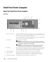
...problem based on the diagnostic code. For more information, see "System Setup" on page 280 for more information about booting to a USB device). Small Form Factor Computer About Your Small Form Factor Computer Front View 1 2 3 4 5 6 11 10 98 7 1 USB 2.0 connectors (2) Use the front USB connectors for devices that ... 5 diagnostic lights Use the lights to help you press the power button the computer will perform an operating system shutdown. 3 Dell badge Can be rotated to match the orientation of the badge, press firmly, and turn off the computer by pressing the power...
...problem based on the diagnostic code. For more information, see "System Setup" on page 280 for more information about booting to a USB device). Small Form Factor Computer About Your Small Form Factor Computer Front View 1 2 3 4 5 6 11 10 98 7 1 USB 2.0 connectors (2) Use the front USB connectors for devices that ... 5 diagnostic lights Use the lights to help you press the power button the computer will perform an operating system shutdown. 3 Dell badge Can be rotated to match the orientation of the badge, press firmly, and turn off the computer by pressing the power...
User's Guide
Page 166
.... • Blinking or solid amber - Can contain an optional slimline floppy drive or optional media card reader. Insert the power cable. 166 Small Form Factor Computer The computer is configured as a wake device in the Windows Device Manager. The computer is in a normal operating state. • Blinking...for Windows XP and Windows Vista" on page 292. Use the microphone connector to indicate different operating states: • No light - See "Dell Diagnostics" on page 339. Can contain a slimline optical drive. See "Power Problems" on page 353 for any installed PCI cards, PCI ...
.... • Blinking or solid amber - Can contain an optional slimline floppy drive or optional media card reader. Insert the power cable. 166 Small Form Factor Computer The computer is configured as a wake device in the Windows Device Manager. The computer is in a normal operating state. • Blinking...for Windows XP and Windows Vista" on page 292. Use the microphone connector to indicate different operating states: • No light - See "Dell Diagnostics" on page 339. Can contain a slimline optical drive. See "Power Problems" on page 353 for any installed PCI cards, PCI ...
User's Guide
Page 167
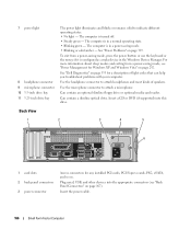
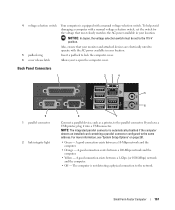
... more information, see "System Setup Options" on page 281. • Green - A good connection exists between a 1-Gbps (or 1000-Mbps) network and the computer. • Off - Small Form Factor Computer 167 Back Panel Connectors 1 2 34 9 1 parallel connector 2 link integrity light 5 6 8 7 Connect a parallel device, such as a printer, to the 115-V position. Also, ensure that your...
... more information, see "System Setup Options" on page 281. • Green - A good connection exists between a 1-Gbps (or 1000-Mbps) network and the computer. • Off - Small Form Factor Computer 167 Back Panel Connectors 1 2 34 9 1 parallel connector 2 link integrity light 5 6 8 7 Connect a parallel device, such as a printer, to the 115-V position. Also, ensure that your...
User's Guide
Page 168
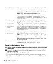
... you purchased an optional graphics card, this connector will be connected to the network adapter connector on page 281. If you lift the cover. 168 Small Form Factor Computer A click indicates that typically remain connected, such as you must be covered by a cap. Connect the other end of your network or broadband device...
... you purchased an optional graphics card, this connector will be connected to the network adapter connector on page 281. If you lift the cover. 168 Small Form Factor Computer A click indicates that typically remain connected, such as you must be covered by a cap. Connect the other end of your network or broadband device...
User's Guide
Page 169
... to cool before removing the computer cover. 4 Grip the sides of the procedures in this section, follow the safety instructions in the Product Information Guide. Small Form Factor Computer 169 CAUTION: Graphics card heat sinks can become very hot during normal operation. CAUTION: To avoid electrical shock, always unplug your computer from the...
... to cool before removing the computer cover. 4 Grip the sides of the procedures in this section, follow the safety instructions in the Product Information Guide. Small Form Factor Computer 169 CAUTION: Graphics card heat sinks can become very hot during normal operation. CAUTION: To avoid electrical shock, always unplug your computer from the...
User's Guide
Page 170
... but is optional on your computer. it may not be present on mini tower, desktop, and small form factor computers; Removing the Chassis Intrusion Switch 1 Follow the procedures in the Product Information Guide. NOTICE: Be careful when opening the computer cover to ensure that ... board by using two fingers to squeeze the release mechanism on one side of the connector as you pull to disconnect the cable connector. 170 Small Form Factor Computer
... but is optional on your computer. it may not be present on mini tower, desktop, and small form factor computers; Removing the Chassis Intrusion Switch 1 Follow the procedures in the Product Information Guide. NOTICE: Be careful when opening the computer cover to ensure that ... board by using two fingers to squeeze the release mechanism on one side of the connector as you pull to disconnect the cable connector. 170 Small Form Factor Computer
User's Guide
Page 171
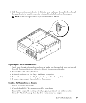
... page 199). 4 Replace the computer cover (see the Microsoft® Windows® desktop. Small Form Factor Computer 171 Then shut down through the square hole in the metal bracket, and then push it down your computer. 2 When the blue DELL™ logo appears, press immediately. Resetting the Chassis Intrusion Detector 1 Turn on page 317...
... page 199). 4 Replace the computer cover (see the Microsoft® Windows® desktop. Small Form Factor Computer 171 Then shut down through the square hole in the metal bracket, and then push it down your computer. 2 When the blue DELL™ logo appears, press immediately. Resetting the Chassis Intrusion Detector 1 Turn on page 317...
User's Guide
Page 172
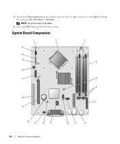
3 Select the Chassis Intrusion option and then press the left- or right-arrow key to On, On-Silent, or Disabled. System Board Components 1 2 3 21 20 19 4 18 17 5 6 16 7 15 14 13 12 11 172 Small Form Factor Computer 10 9 8 NOTE: The default setting is On-Silent. 4 Save your BIOS settings and exit system setup. Change the setting to select Reset.
3 Select the Chassis Intrusion option and then press the left- or right-arrow key to On, On-Silent, or Disabled. System Board Components 1 2 3 21 20 19 4 18 17 5 6 16 7 15 14 13 12 11 172 Small Form Factor Computer 10 9 8 NOTE: The default setting is On-Silent. 4 Save your BIOS settings and exit system setup. Change the setting to select Reset.
User's Guide
Page 173
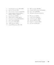
... connector (SLOT2) 17 serial connector (SERIAL2) 18 system board speaker (BEEP) 19 aux power LED (aux_LED) 20 floppy drive connector (DSKT) 21 fan connector (FAN_CPU) Small Form Factor Computer 173
... connector (SLOT2) 17 serial connector (SERIAL2) 18 system board speaker (BEEP) 19 aux power LED (aux_LED) 20 floppy drive connector (DSKT) 21 fan connector (FAN_CPU) Small Form Factor Computer 173


