
Quick Reference Guide
Page 26
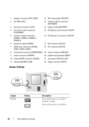
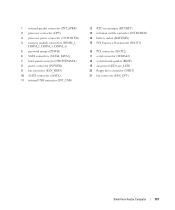
1 speaker connector (INT_SPKR) 12 RTC reset jumper (RTCRST) 2 fan (FAN_CPU) 13 intrusion switch connector (INTRUDER) 3 processor connector (CPU) 14 battery socket (BATTERY) 4 processor power connector (12VPOWER) 15 PCI Express x16 connector (SLOT1) 5 memory module connectors (DIMM_1, DIMM_2, DIMM_3, DIMM_4) 16 PCI Express x1 connector (SLOT4) 6 password jumper (...
1 speaker connector (INT_SPKR) 12 RTC reset jumper (RTCRST) 2 fan (FAN_CPU) 13 intrusion switch connector (INTRUDER) 3 processor connector (CPU) 14 battery socket (BATTERY) 4 processor power connector (12VPOWER) 15 PCI Express x16 connector (SLOT1) 5 memory module connectors (DIMM_1, DIMM_2, DIMM_3, DIMM_4) 16 PCI Express x1 connector (SLOT4) 6 password jumper (...
Quick Reference Guide
Page 47
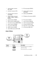
... enabled (default setting). 1 internal speaker connector (INT_SPKR) 12 RTC reset jumper (RTCRST) 2 processor connector (CPU) 13 intrusion switch connector (INTRUDER) 3 processor power connector (12VPOWER) 14 battery socket (BATTERY) 4 memory module connectors (DIMM_1, DIMM_2, DIMM_3, DIMM_4) 15 PCI Express x16 connector (SLOT1) 5 password jumper (PSWD) 16 PCI connector (SLOT2) 6 SATA connectors (SATA0, SATA1...
... enabled (default setting). 1 internal speaker connector (INT_SPKR) 12 RTC reset jumper (RTCRST) 2 processor connector (CPU) 13 intrusion switch connector (INTRUDER) 3 processor power connector (12VPOWER) 14 battery socket (BATTERY) 4 memory module connectors (DIMM_1, DIMM_2, DIMM_3, DIMM_4) 15 PCI Express x16 connector (SLOT1) 5 password jumper (PSWD) 16 PCI connector (SLOT2) 6 SATA connectors (SATA0, SATA1...
Quick Reference Guide
Page 60
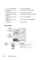
... setting). 1 fan connector (FAN_FRONT) 2 internal speaker connector (INT_SPKR) 3 system board speaker (BEEP) 4 channel B memory connector (DIMM_2) 5 channel A memory connector (DIMM_1) 6 SATA data cable connector (SATA0) 7 battery (BATT) 8 password jumper (PSWD) 9 hard drive fan connector (FAN_HDD) 10 clear CMOS jumper (RTCRST) 11 hard drive power connector (SATA_PWR) 12 fan connector (FAN_REAR) 13...
... setting). 1 fan connector (FAN_FRONT) 2 internal speaker connector (INT_SPKR) 3 system board speaker (BEEP) 4 channel B memory connector (DIMM_2) 5 channel A memory connector (DIMM_1) 6 SATA data cable connector (SATA0) 7 battery (BATT) 8 password jumper (PSWD) 9 hard drive fan connector (FAN_HDD) 10 clear CMOS jumper (RTCRST) 11 hard drive power connector (SATA_PWR) 12 fan connector (FAN_REAR) 13...
User's Guide
Page 12
... Hard Drive Failure (RAID 1) Using the Intel Matrix Storage Manager 300 Migrating to a RAID Level 0 Configuration 301 Migrating to a RAID Level 1 Configuration 301 10 Battery Replacing the Battery 303 11 Replacing the System Board Removing the System Board: Mini Tower, Desktop, Small Form Factor, and Ultra Small Form Factor Computers 307 Mini...
... Hard Drive Failure (RAID 1) Using the Intel Matrix Storage Manager 300 Migrating to a RAID Level 0 Configuration 301 Migrating to a RAID Level 1 Configuration 301 10 Battery Replacing the Battery 303 11 Replacing the System Board Removing the System Board: Mini Tower, Desktop, Small Form Factor, and Ultra Small Form Factor Computers 307 Mini...
User's Guide
Page 13
... Vista 327 Setting Up a Home and Office Network 328 Connecting to a Network Adapter 328 Network Setup 328 Windows XP 328 Windows Vista 329 17 Troubleshooting Battery Problems 331 Card Problems 331 Drive Problems 332 Optical drive problems 333 Problems writing to an optical drive 333 Hard drive problems 333 E-Mail, Modem...
... Vista 327 Setting Up a Home and Office Network 328 Connecting to a Network Adapter 328 Network Setup 328 Windows XP 328 Windows Vista 329 17 Troubleshooting Battery Problems 331 Card Problems 331 Drive Problems 332 Optical drive problems 333 Problems writing to an optical drive 333 Hard drive problems 333 E-Mail, Modem...

User's Guide
Page 32
System Board Components 1 2 3 22 21 20 19 18 17 16 15 4 5 6 7 8 14 13 12 1 speaker connector (INT_SPKR) 2 fan (FAN_CPU) 3 processor connector (CPU) 4 processor power connector (12VPOWER) 5 memory module connectors (DIMM_1, DIMM_2, DIMM_3, DIMM_4) 11 10 9 12 RTC reset jumper (RTCRST) 13 intrusion switch connector (INTRUDER) 14 battery socket (BATTERY) 15 PCI Express x16 connector (SLOT1) 16 PCI Express x1 connector (SLOT4) 32 Mini Tower Computer
System Board Components 1 2 3 22 21 20 19 18 17 16 15 4 5 6 7 8 14 13 12 1 speaker connector (INT_SPKR) 2 fan (FAN_CPU) 3 processor connector (CPU) 4 processor power connector (12VPOWER) 5 memory module connectors (DIMM_1, DIMM_2, DIMM_3, DIMM_4) 11 10 9 12 RTC reset jumper (RTCRST) 13 intrusion switch connector (INTRUDER) 14 battery socket (BATTERY) 15 PCI Express x16 connector (SLOT1) 16 PCI Express x1 connector (SLOT4) 32 Mini Tower Computer
User's Guide
Page 38
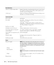
...) solid green light indicates network connection Link integrity light (on the system board Power DC power supply: Wattage Heat dissipation Voltage Backup battery NOTE: Power consumption from an AC power source can be zero when the computer is unplugged from the AC power source. 305 W...light for 100-Mb operation; blinking green indicates sleep mode; solid green indicates power-on front of power from the internal coin cell battery even when the computer is calculated based upon the power supply rating. blinking amber indicates a problem with an installed device; solid amber ...
...) solid green light indicates network connection Link integrity light (on the system board Power DC power supply: Wattage Heat dissipation Voltage Backup battery NOTE: Power consumption from an AC power source can be zero when the computer is unplugged from the AC power source. 305 W...light for 100-Mb operation; blinking green indicates sleep mode; solid green indicates power-on front of power from the internal coin cell battery even when the computer is calculated based upon the power supply rating. blinking amber indicates a problem with an installed device; solid amber ...
User's Guide
Page 101
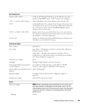
... that allows the user to run hard drive and system diagnostics displays the Management Engine BIOS Extension settings screen that power source, but the internal battery does draw a minute amount of power from the power supply even when the computer is unplugged from the AC power source. 280 W Desktop Computer Specifications...
... that allows the user to run hard drive and system diagnostics displays the Management Engine BIOS Extension settings screen that power source, but the internal battery does draw a minute amount of power from the power supply even when the computer is unplugged from the AC power source. 280 W Desktop Computer Specifications...
User's Guide
Page 102
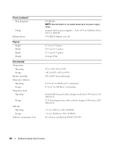
Power (continued) Heat dissipation Voltage Backup battery Physical Height Width Depth Weight Environmental Temperature: Operating Storage Relative humidity Maximum vibration: Operating Storage Maximum shock: Operating Storage Altitude: Operating Storage Airborne contaminant level ...
Power (continued) Heat dissipation Voltage Backup battery Physical Height Width Depth Weight Environmental Temperature: Operating Storage Relative humidity Maximum vibration: Operating Storage Maximum shock: Operating Storage Altitude: Operating Storage Airborne contaminant level ...
User's Guide
Page 173
... (POWER) 9 fan connector (FAN_HDD) 10 eSATA connector (eSATA) 11 internal USB connector (INT_USB) 12 RTC reset jumper (RTCRST) 13 intrusion switch connector (INTRUDER) 14 battery socket (BATTERY) 15 PCI Express x16 connector (SLOT1) 16 PCI connector (SLOT2) 17 serial connector (SERIAL2) 18 system board speaker (BEEP) 19 aux power LED (aux_LED) 20...
... (POWER) 9 fan connector (FAN_HDD) 10 eSATA connector (eSATA) 11 internal USB connector (INT_USB) 12 RTC reset jumper (RTCRST) 13 intrusion switch connector (INTRUDER) 14 battery socket (BATTERY) 15 PCI Express x16 connector (SLOT1) 16 PCI connector (SLOT2) 17 serial connector (SERIAL2) 18 system board speaker (BEEP) 19 aux power LED (aux_LED) 20...
User's Guide
Page 178
... 1000-Mb (1-Gb) operation Activity light (on integrated network yellow blinking light adapter) Diagnostic lights four lights on the front panel (See "Dell Diagnostics" on page 353.) Standby power light AUX_PWR on the system board Power DC power supply: Wattage NOTE: Power consumption from an AC ... the AC power source. 275 W 178 Small Form Factor Computer Specifications However, the computer draws minimal power from the internal coin cell battery even when the computer is unplugged from that allows you are running Microsoft® Windows® XP, brings up only) as well as...
... 1000-Mb (1-Gb) operation Activity light (on integrated network yellow blinking light adapter) Diagnostic lights four lights on the front panel (See "Dell Diagnostics" on page 353.) Standby power light AUX_PWR on the system board Power DC power supply: Wattage NOTE: Power consumption from an AC ... the AC power source. 275 W 178 Small Form Factor Computer Specifications However, the computer draws minimal power from the internal coin cell battery even when the computer is unplugged from that allows you are running Microsoft® Windows® XP, brings up only) as well as...
User's Guide
Page 179
... 35,000 ft) G2 or lower as defined by ISA-S71.04-1985 Small Form Factor Computer Specifications 179 Power (continued) Heat dissipation Voltage Backup battery Physical Height Width Depth Weight Environmental Temperature: Operating Storage Relative humidity Maximum vibration: Operating Storage Maximum shock: Operating Storage Altitude: Operating Storage Airborne contaminant level...
... 35,000 ft) G2 or lower as defined by ISA-S71.04-1985 Small Form Factor Computer Specifications 179 Power (continued) Heat dissipation Voltage Backup battery Physical Height Width Depth Weight Environmental Temperature: Operating Storage Relative humidity Maximum vibration: Operating Storage Maximum shock: Operating Storage Altitude: Operating Storage Airborne contaminant level...
User's Guide
Page 244
However, the computer draws a minute amount of power from the internal coin cell battery even when the computer is not drawing power from the AC power source. 220 W 751 BTU/hr NOTE: Heat dissipation is unplugged from an AC ... source can be zero when the computer is calculated based upon the power supply rating. Power DC external power supply: Wattage Heat dissipation Voltage Backup battery Physical Without cable cover: Height Width Depth Weight With standard cable cover: Height Width Depth Weight With extended cable cover: Height Width Depth NOTE: Power...
However, the computer draws a minute amount of power from the internal coin cell battery even when the computer is not drawing power from the AC power source. 220 W 751 BTU/hr NOTE: Heat dissipation is unplugged from an AC ... source can be zero when the computer is calculated based upon the power supply rating. Power DC external power supply: Wattage Heat dissipation Voltage Backup battery Physical Without cable cover: Height Width Depth Weight With standard cable cover: Height Width Depth Weight With extended cable cover: Height Width Depth NOTE: Power...

User's Guide
Page 272
... ASF Administrator's Guide, which are available for information about DCM. Battery Low The computer battery has reached a voltage of limits or the fan speed Critical Fan Failure/Generic (rpm) problem has been resolved. Dell OpenManage™ Applications NOTE: Either Dell OpenManage™ applications and Dell™ Client Manager (DCM) are available on some computers) installed...
... ASF Administrator's Guide, which are available for information about DCM. Battery Low The computer battery has reached a voltage of limits or the fan speed Critical Fan Failure/Generic (rpm) problem has been resolved. Dell OpenManage™ Applications NOTE: Either Dell OpenManage™ applications and Dell™ Client Manager (DCM) are available on some computers) installed...
User's Guide
Page 294
..., activate hibernate mode, or turn off hard disks, System stand by, or System hibernates field, and then select a time-out from batteries for your Windows password before the computer exits from a power conservation mode, it returns to run your computer uses when it is on.... 2 In the Performance and maintenance window, click Conserving power on the Hibernate tab. If your computer with minimal power conservation. • Max Battery - If you run with no power conservation). • Minimal Power Management - The Power schemes drop-down menu and click OK. Hibernate Tab ...
..., activate hibernate mode, or turn off hard disks, System stand by, or System hibernates field, and then select a time-out from batteries for your Windows password before the computer exits from a power conservation mode, it returns to run your computer uses when it is on.... 2 In the Performance and maintenance window, click Conserving power on the Hibernate tab. If your computer with minimal power conservation. • Max Battery - If you run with no power conservation). • Minimal Power Management - The Power schemes drop-down menu and click OK. Hibernate Tab ...

User's Guide
Page 303
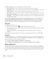
...the procedures in this case, you begin any of your computer, discharge static electricity from the electrical outlet. Battery 303 however, without a battery; Discard used batteries according to components inside your configuration information, found in system setup. 2 Follow the procedures in system setup.... then reconnect the computer, turn it on, and enter system setup (see "Entering System Setup" on page 280). Battery Replacing the Battery CAUTION: Before you must enter system setup (see "Entering System Setup" on page 280) and reset the configuration options....
...the procedures in this case, you begin any of your computer, discharge static electricity from the electrical outlet. Battery 303 however, without a battery; Discard used batteries according to components inside your configuration information, found in system setup. 2 Follow the procedures in system setup.... then reconnect the computer, turn it on, and enter system setup (see "Entering System Setup" on page 280). Battery Replacing the Battery CAUTION: Before you must enter system setup (see "Entering System Setup" on page 280) and reset the configuration options....
User's Guide
Page 304
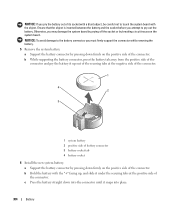
... the "+" facing up out of the securing tabs at the positive side of battery connector 3 battery socket tab 4 battery socket 6 Install the new system battery. a Support the battery connector by pressing down firmly on the positive side of the connector. c Press the battery straight down firmly on the positive side of the connector. Otherwise, you pry...
... the "+" facing up out of the securing tabs at the positive side of battery connector 3 battery socket tab 4 battery socket 6 Install the new system battery. a Support the battery connector by pressing down firmly on the positive side of the connector. c Press the battery straight down firmly on the positive side of the connector. Otherwise, you pry...
User's Guide
Page 305
7 Replace the computer cover (see "Replacing the Computer Cover" on page 317). 8 Enter system setup (see "Entering System Setup" on page 280) and restore the settings you recorded in step 1. 9 Properly dispose of the old battery as described in the Product Information Guide. Battery 305
7 Replace the computer cover (see "Replacing the Computer Cover" on page 317). 8 Enter system setup (see "Entering System Setup" on page 280) and restore the settings you recorded in step 1. 9 Properly dispose of the old battery as described in the Product Information Guide. Battery 305
User's Guide
Page 331
... Guide. CAUTION: Before you set your computer's electronic components. This message may not apply if you begin any of a new battery exploding if it is properly connected. • If an error message appears on the screen, write down the exact message. Discard used...battery only with the same or equivalent type recommended by touching an unpainted metal surface on page 303). If you added or removed a part before the problem started, review the installation procedures and ensure that the part is correctly installed. • If a peripheral device does not work properly, contact Dell...
... Guide. CAUTION: Before you set your computer's electronic components. This message may not apply if you begin any of a new battery exploding if it is properly connected. • If an error message appears on the screen, write down the exact message. Discard used...battery only with the same or equivalent type recommended by touching an unpainted metal surface on page 303). If you added or removed a part before the problem started, review the installation procedures and ensure that the part is correctly installed. • If a peripheral device does not work properly, contact Dell...
User's Guide
Page 352
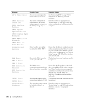
Corrective Action See "Contacting Dell" on page 370 for instructions on page 280), verify the system configuration, and then ...Check the interface cable at both ends. The operating system cannot be low. Message CH-2 Timer Error CMOS Battery State Low CMOS Checksum Failure CMOS System Options Not Set CMOS Display Type Mismatch CMOS Memory Size Mismatch CMOS Time... Cause An error is occurring on the timer on drive A or drive C. Drive A or B is incorrect or the battery charge may need to be replaced. An interrupt channel on page 280) and confirm that drive A or drive C is properly...
Corrective Action See "Contacting Dell" on page 370 for instructions on page 280), verify the system configuration, and then ...Check the interface cable at both ends. The operating system cannot be low. Message CH-2 Timer Error CMOS Battery State Low CMOS Checksum Failure CMOS System Options Not Set CMOS Display Type Mismatch CMOS Memory Size Mismatch CMOS Time... Cause An error is occurring on the timer on drive A or drive C. Drive A or B is incorrect or the battery charge may need to be replaced. An interrupt channel on page 280) and confirm that drive A or drive C is properly...


