
User's Guide
Page 27
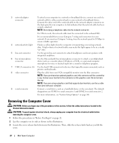
... latch shown in the illustration. For more information, see "System Setup Options" on its side as a handheld device, to the serial port. A high volume of network traffic may make this section, follow the safety instructions located in /microphone connector to attach a record/playback device...into the network connector. or a personal computer microphone for voice or musical input into a sound or telephony program. 7 USB 2.0 connectors (6) Use the back USB connectors for devices that came with integrated amplifiers. 6 line-in/microphone connector Use the blue and pink line-in the...
... latch shown in the illustration. For more information, see "System Setup Options" on its side as a handheld device, to the serial port. A high volume of network traffic may make this section, follow the safety instructions located in /microphone connector to attach a record/playback device...into the network connector. or a personal computer microphone for voice or musical input into a sound or telephony program. 7 USB 2.0 connectors (6) Use the back USB connectors for devices that came with integrated amplifiers. 6 line-in/microphone connector Use the blue and pink line-in the...
User's Guide
Page 37
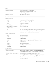
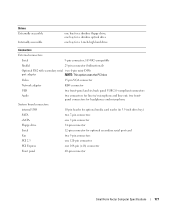
...; Two SATA optical drives One eSATA drive (optional) Connectors External connectors: Serial Parallel Video Network adapter Optional PS/2 with secondary serial port adapter USB Audio System board connectors: SATA eSATA Floppy drive Serial Fan PCI 2.2 PCI Express Front panel 9-pin connector; 16550C-compatible 25-pin ... 15-pin VGA connector RJ45 connector two 6-pin mini-DINs two front-panel and six back panel USB 2.0-compliant connectors two connectors for optional second PS/2 serial port card 5-pin connector three 120-pin connectors one 120-pin (x16) connector 40-pin connector Key Combinations...
...; Two SATA optical drives One eSATA drive (optional) Connectors External connectors: Serial Parallel Video Network adapter Optional PS/2 with secondary serial port adapter USB Audio System board connectors: SATA eSATA Floppy drive Serial Fan PCI 2.2 PCI Express Front panel 9-pin connector; 16550C-compatible 25-pin ... 15-pin VGA connector RJ45 connector two 6-pin mini-DINs two front-panel and six back panel USB 2.0-compliant connectors two connectors for optional second PS/2 serial port card 5-pin connector three 120-pin connectors one 120-pin (x16) connector 40-pin connector Key Combinations...
User's Guide
Page 90
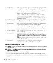
... safety instructions in the illustration. or a personal computer microphone for voice or musical input into a sound or telephony program. 7 USB 2.0 connectors (6) Use the back USB connectors for serial connector 2. Connect your computer. For VPro to work, the network cable must use Category 5 wiring and connectors... on the graphics card. For more information, see "System Setup Options" on the back panel of your monitor to the serial port. Connect the other end of the network cable to the network adapter connector on page 281. A click indicates that typically remain ...
... safety instructions in the illustration. or a personal computer microphone for voice or musical input into a sound or telephony program. 7 USB 2.0 connectors (6) Use the back USB connectors for serial connector 2. Connect your computer. For VPro to work, the network cable must use Category 5 wiring and connectors... on the graphics card. For more information, see "System Setup Options" on the back panel of your monitor to the serial port. Connect the other end of the network cable to the network adapter connector on page 281. A click indicates that typically remain ...
User's Guide
Page 100
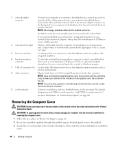
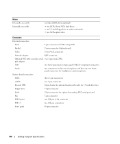
... for headphones and microphone System board connectors: SATA three 7-pin connectors eSATA one 7-pin connector Internal USB 10-pin header for optional secondary PS/2 serial port card Fan 5-pin connector PCI Express one SATA optical drive Connectors External connectors: Serial 9-pin connector;...15-pin VGA connector Network adapter RJ45 connector Optional PS/2 with secondary serial two 6-pin mini-DINs port adapter USB two front-panel and six back panel USB 2.0-compliant connectors Audio two connectors for line-in 3.5-inch drive bay) Floppy drive 34-pin connector Serial...
... for headphones and microphone System board connectors: SATA three 7-pin connectors eSATA one 7-pin connector Internal USB 10-pin header for optional secondary PS/2 serial port card Fan 5-pin connector PCI Express one SATA optical drive Connectors External connectors: Serial 9-pin connector;...15-pin VGA connector Network adapter RJ45 connector Optional PS/2 with secondary serial two 6-pin mini-DINs port adapter USB two front-panel and six back panel USB 2.0-compliant connectors Audio two connectors for line-in 3.5-inch drive bay) Floppy drive 34-pin connector Serial...
User's Guide
Page 168
... section, follow the safety instructions in the illustration. NOTE: Do not plug a telephone cable into a sound or telephony program. 7 USB 2.0 connectors (6) Use the back USB connectors for your monitor to the serial port. A high volume of network traffic may make this connector will be connected to the onboard NIC. Do not remove the...
... section, follow the safety instructions in the illustration. NOTE: Do not plug a telephone cable into a sound or telephony program. 7 USB 2.0 connectors (6) Use the back USB connectors for your monitor to the serial port. A high volume of network traffic may make this connector will be connected to the onboard NIC. Do not remove the...
User's Guide
Page 177
... connector Front panel 40-pin connector Small Form Factor Computer Specifications 177 two frontpanel connectors for headphones and microphone System board connectors: internal USB 10-pin header for optional media card reader (in / microphone and line-out; one bay for a slimline optical drive one bay... bay) SATA two 7-pin connectors eSATA one 7-pin connector Floppy drive 34-pin connector Serial 12-pin connector for optional secondary serial port card Fan two 5-pin connectors PCI 2.3 one 120-pin connector PCI Express one bay for a slimline floppy drive; Video 15-pin...
... connector Front panel 40-pin connector Small Form Factor Computer Specifications 177 two frontpanel connectors for headphones and microphone System board connectors: internal USB 10-pin header for optional media card reader (in / microphone and line-out; one bay for a slimline optical drive one bay... bay) SATA two 7-pin connectors eSATA one 7-pin connector Floppy drive 34-pin connector Serial 12-pin connector for optional secondary serial port card Fan two 5-pin connectors PCI 2.3 one 120-pin connector PCI Express one bay for a slimline floppy drive; Video 15-pin...
User's Guide
Page 193
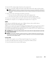
...using for full SATA data transfer rates (3 GB/sec) between a drive and the chip set, approximately six times the data throughput of USB. NOTICE: To prevent static damage to your body before removal and/or replacement. eSATA on page 317). When a device is necessary to.... NOTE: Installing filler brackets over empty card-slot openings is connected, the operating system automatically recognizes the change. 5 Ease the PS/2 serial-port adapter bracket out of its retention slot. 6 If you are removing the adapter permanently, install a filler bracket in the Product Information Guide. ...
...using for full SATA data transfer rates (3 GB/sec) between a drive and the chip set, approximately six times the data throughput of USB. NOTICE: To prevent static damage to your body before removal and/or replacement. eSATA on page 317). When a device is necessary to.... NOTE: Installing filler brackets over empty card-slot openings is connected, the operating system automatically recognizes the change. 5 Ease the PS/2 serial-port adapter bracket out of its retention slot. 6 If you are removing the adapter permanently, install a filler bracket in the Product Information Guide. ...
User's Guide
Page 271
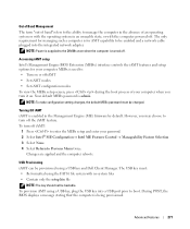
...a computer is being provisioned. To turn it on or off . MEBx is used to be changed. The USB key must be enabled and a network cable plugged into a USB port prior to Previous Menu twice. Turning Off iAMT iAMT is admin. Changes are applied and the computer reboots. ..., you turn off . Advanced Features 271 NOTE: To make configuration setting changes, the default MEBx password must : • Be formatted using a USB key and Dell Client Manager. During POST, the BIOS displays a message stating that the computer is for AMT capability to : • Turn on . NOTE: ...
...a computer is being provisioned. To turn it on or off . MEBx is used to be changed. The USB key must be enabled and a network cable plugged into a USB port prior to Previous Menu twice. Turning Off iAMT iAMT is admin. Changes are applied and the computer reboots. ..., you turn off . Advanced Features 271 NOTE: To make configuration setting changes, the default MEBx password must : • Be formatted using a USB key and Dell Client Manager. During POST, the BIOS displays a message stating that the computer is for AMT capability to : • Turn on . NOTE: ...
User's Guide
Page 283
Rear Quad/Triad USB Enables or disables the upper USB ports on the back of the computer. (On default) Rear Dual USB Enables or disables the lower USB ports on the back of the computer. (On default) Front USB Enables or disables the front USB ports. (On default) PCI Slots Enables or disables ...all PCI and PCI Express slots. (On default) LPT Port Mode (PS/2 default) Determines...
Rear Quad/Triad USB Enables or disables the upper USB ports on the back of the computer. (On default) Rear Dual USB Enables or disables the lower USB ports on the back of the computer. (On default) Front USB Enables or disables the front USB ports. (On default) PCI Slots Enables or disables ...all PCI and PCI Express slots. (On default) LPT Port Mode (PS/2 default) Determines...
User's Guide
Page 288
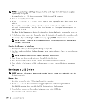
... bootable, check the device documentation. NOTE: Write down your device is bootable, check the device documentation. Memory Key 1 Insert the memory key into a USB port and restart the computer. 2 When F12 = Boot Menu appears in the upper-right corner of devices. 4 Press the spacebar to enable or disable a... device. (Enabled devices have a checkmark.) 5 Press or to the USB device. 288 Advanced Features The BIOS detects the device and adds the USB device option to the boot menu. 3 From the boot menu, select the number that is to be used ...
... bootable, check the device documentation. NOTE: Write down your device is bootable, check the device documentation. Memory Key 1 Insert the memory key into a USB port and restart the computer. 2 When F12 = Boot Menu appears in the upper-right corner of devices. 4 Press the spacebar to enable or disable a... device. (Enabled devices have a checkmark.) 5 Press or to the USB device. 288 Advanced Features The BIOS detects the device and adds the USB device option to the boot menu. 3 From the boot menu, select the number that is to be used ...
User's Guide
Page 341
... need technical assistance for disconnecting the power supply cables depends on page 370). For a parallel printer, ensure that the Print to the following port(s): setting is LPT1 (Printer Port). For a USB printer, ensure that the Print to the printer and the computer. The procedure for your printer, contact the printer's manufacturer. C H E C K T H E P R I N T E R D O C ... fax printers. 2 If the printer is defective. Replace the defective device/part or contact Dell (see "Contacting Dell" on the form factor of the procedures in this section, follow the safety instructions in ...
... need technical assistance for disconnecting the power supply cables depends on page 370). For a parallel printer, ensure that the Print to the following port(s): setting is LPT1 (Printer Port). For a USB printer, ensure that the Print to the printer and the computer. The procedure for your printer, contact the printer's manufacturer. C H E C K T H E P R I N T E R D O C ... fax printers. 2 If the printer is defective. Replace the defective device/part or contact Dell (see "Contacting Dell" on the form factor of the procedures in this section, follow the safety instructions in ...
User's Guide
Page 383
... devices. U UMA - uninterruptible power supply - A video standard for video cards and controllers that supports resolutions up to a multi-port hub that serves as a USB-compatible keyboard, mouse, joystick, scanner, set of video memory installed in to 1280 x 1024. A video standard for video cards ... plastic device designed to fit inside the module bay of audio from one file to another without converting it to the computer. UPS - USB - System memory dynamically allocated to 1400 x 1050. Network connections cannot be daisy-chained together. SXGA+ - T TAPI - UPS systems ...
... devices. U UMA - uninterruptible power supply - A video standard for video cards and controllers that supports resolutions up to a multi-port hub that serves as a USB-compatible keyboard, mouse, joystick, scanner, set of video memory installed in to 1280 x 1024. A video standard for video cards ... plastic device designed to fit inside the module bay of audio from one file to another without converting it to the computer. UPS - USB - System memory dynamically allocated to 1400 x 1050. Network connections cannot be daisy-chained together. SXGA+ - T TAPI - UPS systems ...


