
Quick Reference Guide
Page 3
... Up Your Monitor 12 Power Connections 12 Before You Begin 13 Recommended Tools 13 Turning Off Your Computer 13 Before Working Inside Your Computer 14 Mini Tower Computer 16 System Views 16 Removing the Computer Cover 22 Inside Your Computer 24 System Board Components 25 Jumper Settings 26 Desktop Computer 27 System...
... Up Your Monitor 12 Power Connections 12 Before You Begin 13 Recommended Tools 13 Turning Off Your Computer 13 Before Working Inside Your Computer 14 Mini Tower Computer 16 System Views 16 Removing the Computer Cover 22 Inside Your Computer 24 System Board Components 25 Jumper Settings 26 Desktop Computer 27 System...

Quick Reference Guide
Page 13
... in this document may require the following conditions exist: • You have performed the steps in "Turning Off Your Computer" on page 13 and "Mini Tower Computer" on page 16. • You have read the safety information in reverse order. In the Microsoft® Windows Vista™ operating system, ...and installing the components in the lower-right corner of the desktop, click the arrow in your computer. The computer turns off your Dell™ Product Information Guide. • A component can be replaced by performing the removal procedure in your computer. 1 Shut down .
... in this document may require the following conditions exist: • You have performed the steps in "Turning Off Your Computer" on page 13 and "Mini Tower Computer" on page 16. • You have read the safety information in reverse order. In the Microsoft® Windows Vista™ operating system, ...and installing the components in the lower-right corner of the desktop, click the arrow in your computer. The computer turns off your Dell™ Product Information Guide. • A component can be replaced by performing the removal procedure in your computer. 1 Shut down .
Quick Reference Guide
Page 15
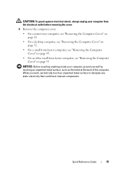
.... Quick Reference Guide 15 NOTICE: Before touching anything inside your computer from the electrical outlet before removing the cover. 6 Remove the computer cover. • For a mini tower computer, see "Removing the Computer Cover" on page 22. • For a desktop computer, see "Removing the Computer Cover" on page 32. • For a small form...
.... Quick Reference Guide 15 NOTICE: Before touching anything inside your computer from the electrical outlet before removing the cover. 6 Remove the computer cover. • For a mini tower computer, see "Removing the Computer Cover" on page 22. • For a desktop computer, see "Removing the Computer Cover" on page 32. • For a small form...
Quick Reference Guide
Page 16
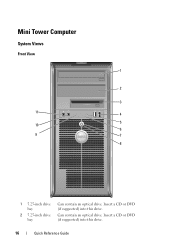
Insert a CD or DVD (if supported) into this drive. Insert a CD or DVD (if supported) into this drive. 16 Quick Reference Guide Can contain an optical drive. Mini Tower Computer System Views Front View 1 2 3 11 4 10 5 6 9 7 8 1 5.25-inch drive bay 2 5.25-inch drive bay Can contain an optical drive.
Insert a CD or DVD (if supported) into this drive. Insert a CD or DVD (if supported) into this drive. 16 Quick Reference Guide Can contain an optical drive. Mini Tower Computer System Views Front View 1 2 3 11 4 10 5 6 9 7 8 1 5.25-inch drive bay 2 5.25-inch drive bay Can contain an optical drive.
User's Guide
Page 3
... Information 2 Before You Begin Recommended Tools 21 Turning Off Your Computer 21 Before Working Inside Your Computer 21 3 Mini Tower Computer About Your Mini Tower Computer 23 Front View 23 Back View 25 Back Panel Connectors 26 Removing the Computer Cover 27 Inside Your Computer ...29 Removing the Chassis Intrusion Switch 30 Replacing the Chassis Intrusion Switch 30 Resetting the Chassis Intrusion Detector 31 System Board Components 32 4 Mini Tower Computer Specifications Cards 41 Installing a PCI or PCI Express Card 41 Removing a PCI or PCI Express Card 45 PS/2 Serial Port ...
... Information 2 Before You Begin Recommended Tools 21 Turning Off Your Computer 21 Before Working Inside Your Computer 21 3 Mini Tower Computer About Your Mini Tower Computer 23 Front View 23 Back View 25 Back Panel Connectors 26 Removing the Computer Cover 27 Inside Your Computer ...29 Removing the Chassis Intrusion Switch 30 Replacing the Chassis Intrusion Switch 30 Resetting the Chassis Intrusion Detector 31 System Board Components 32 4 Mini Tower Computer Specifications Cards 41 Installing a PCI or PCI Express Card 41 Removing a PCI or PCI Express Card 45 PS/2 Serial Port ...
User's Guide
Page 12
... 301 10 Battery Replacing the Battery 303 11 Replacing the System Board Removing the System Board: Mini Tower, Desktop, Small Form Factor, and Ultra Small Form Factor Computers 307 Mini Tower System Board Screws 308 Desktop System Board Screws 309 Small Form Factor System Board Screws 310 Ultra... Small Form Factor System Board Screws 311 Replacing the System Board: Mini Tower, Desktop, Small Form Factor, and Ultra Small Form Factor Computers 311 12 Memory DDR2 Memory Overview 313 Addressing Memory Configurations 314...
... 301 10 Battery Replacing the Battery 303 11 Replacing the System Board Removing the System Board: Mini Tower, Desktop, Small Form Factor, and Ultra Small Form Factor Computers 307 Mini Tower System Board Screws 308 Desktop System Board Screws 309 Small Form Factor System Board Screws 310 Ultra... Small Form Factor System Board Screws 311 Replacing the System Board: Mini Tower, Desktop, Small Form Factor, and Ultra Small Form Factor Computers 311 12 Memory DDR2 Memory Overview 313 Addressing Memory Configurations 314...
User's Guide
Page 22
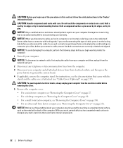
...your computer. NOTICE: To avoid damaging the computer, perform the following steps before you connect a cable, ensure that is not authorized by Dell is not covered by touching an unpainted metal surface, such as a processor by its edges, not by its strain-relief loop, not ... are disconnecting this section, follow the safety instructions in on the locking tabs before removing the cover. 5 Remove the computer cover. • For a mini tower computer, see "Removing the Computer Cover" on page 27. • For a desktop computer, see "Removing the Computer Cover" on page 90. •...
...your computer. NOTICE: To avoid damaging the computer, perform the following steps before you connect a cable, ensure that is not authorized by Dell is not covered by touching an unpainted metal surface, such as a processor by its edges, not by its strain-relief loop, not ... are disconnecting this section, follow the safety instructions in on the locking tabs before removing the cover. 5 Remove the computer cover. • For a mini tower computer, see "Removing the Computer Cover" on page 27. • For a desktop computer, see "Removing the Computer Cover" on page 90. •...

User's Guide
Page 23
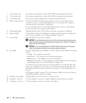
Mini Tower Computer About Your Mini Tower Computer Front View 1 2 3 11 4 10 5 6 9 7 8 23 Mini Tower Computer
Mini Tower Computer About Your Mini Tower Computer Front View 1 2 3 11 4 10 5 6 9 7 8 23 Mini Tower Computer
User's Guide
Page 24
... off . • Steady green - Can contain an optical drive. For more information. Insert a CD or DVD (if supported) into this button to attach a microphone. 24 Mini Tower Computer Can contain an optional floppy drive or optional media card reader. See "Diagnostic Lights" on the computer.
... off . • Steady green - Can contain an optical drive. For more information. Insert a CD or DVD (if supported) into this button to attach a microphone. 24 Mini Tower Computer Can contain an optional floppy drive or optional media card reader. See "Diagnostic Lights" on the computer.
User's Guide
Page 25
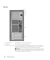
... cover. 3 voltage selection switch Your computer is equipped with a manual voltage-selection switch, set to operate with the AC power available in your location. 25 Mini Tower Computer To help avoid damaging a computer with a manual voltage-selection switch.
... cover. 3 voltage selection switch Your computer is equipped with a manual voltage-selection switch, set to operate with the AC power available in your location. 25 Mini Tower Computer To help avoid damaging a computer with a manual voltage-selection switch.
User's Guide
Page 26
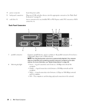
... it into the appropriate connectors. The computer is automatically disabled if the computer detects an installed card containing a parallel connector configured to the network. 26 Mini Tower Computer Back Panel Connectors 1 2 34 5 9 1 parallel connector 2 link integrity light 6 8 7 Connect a parallel device, such as a printer, to the parallel connector. For more information, see "System...
... it into the appropriate connectors. The computer is automatically disabled if the computer detects an installed card containing a parallel connector configured to the network. 26 Mini Tower Computer Back Panel Connectors 1 2 34 5 9 1 parallel connector 2 link integrity light 6 8 7 Connect a parallel device, such as a printer, to the parallel connector. For more information, see "System...
User's Guide
Page 27
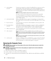
..., follow the safety instructions located in the illustration. Connect your computer from your network or broadband device. A click indicates that you lift the cover. 27 Mini Tower Computer NOTE: Do not plug a telephone cable into the network connector. The default designations are using a graphics card that supports dual monitors, use the y-cable...
..., follow the safety instructions located in the illustration. Connect your computer from your network or broadband device. A click indicates that you lift the cover. 27 Mini Tower Computer NOTE: Do not plug a telephone cable into the network connector. The default designations are using a graphics card that supports dual monitors, use the y-cable...
User's Guide
Page 28
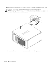
4 Grip the sides of the computer cover and pivot the cover up using the hinge tabs as leverage points. 5 Remove the cover from the hinge tabs and set it . 1 2 3 1 security cable slot 2 cover release latch 3 padlock ring 28 Mini Tower Computer CAUTION: Graphics card heat sinks can become very hot during normal operation. Ensure that a graphics card heat sink has had sufficient time to cool before you touch it aside on a soft nonabrasive surface.
4 Grip the sides of the computer cover and pivot the cover up using the hinge tabs as leverage points. 5 Remove the cover from the hinge tabs and set it . 1 2 3 1 security cable slot 2 cover release latch 3 padlock ring 28 Mini Tower Computer CAUTION: Graphics card heat sinks can become very hot during normal operation. Ensure that a graphics card heat sink has had sufficient time to cool before you touch it aside on a soft nonabrasive surface.
User's Guide
Page 29
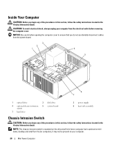
... the procedures in this section, follow the safety instructions located in the Product Information Guide. CAUTION: To avoid electrical shock, always unplug your computer. 29 Mini Tower Computer it may not be present on mini tower, desktop and small form factor computers;
... the procedures in this section, follow the safety instructions located in the Product Information Guide. CAUTION: To avoid electrical shock, always unplug your computer. 29 Mini Tower Computer it may not be present on mini tower, desktop and small form factor computers;
User's Guide
Page 30
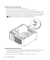
... page 27). 3 Disconnect the chassis intrusion switch cable from the system board by using two fingers to squeeze the release mechanism on page 317). 30 Mini Tower Computer Removing the Chassis Intrusion Switch 1 Follow the procedures in "Before You Begin" on page 21. 2 Remove the computer cover (see "Replacing the Computer Cover...
... page 27). 3 Disconnect the chassis intrusion switch cable from the system board by using two fingers to squeeze the release mechanism on page 317). 30 Mini Tower Computer Removing the Chassis Intrusion Switch 1 Follow the procedures in "Before You Begin" on page 21. 2 Remove the computer cover (see "Replacing the Computer Cover...
User's Guide
Page 31
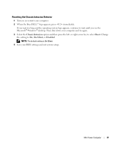
Mini Tower Computer 31 Resetting the Chassis Intrusion Detector 1 Turn on (or restart) your computer and try again. 3 Select the Chassis Intrusion option and then press the left- Then shut down your computer. 2 When the blue DELL™ logo appears, press immediately. Change the setting to wait until you see the Microsoft® Windows® desktop. If you wait too long and the operating system logo appears, continue to On, On-Silent, or Disabled. NOTE: The default setting is On-Silent. 4 Save your BIOS settings and exit system setup. or right-arrow key to select Reset.
Mini Tower Computer 31 Resetting the Chassis Intrusion Detector 1 Turn on (or restart) your computer and try again. 3 Select the Chassis Intrusion option and then press the left- Then shut down your computer. 2 When the blue DELL™ logo appears, press immediately. Change the setting to wait until you see the Microsoft® Windows® desktop. If you wait too long and the operating system logo appears, continue to On, On-Silent, or Disabled. NOTE: The default setting is On-Silent. 4 Save your BIOS settings and exit system setup. or right-arrow key to select Reset.

User's Guide
Page 32
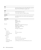
System Board Components 1 2 3 22 21 20 19 18 17 16 15 4 5 6 7 8 14 13 12 1 speaker connector (INT_SPKR) 2 fan (FAN_CPU) 3 processor connector (CPU) 4 processor power connector (12VPOWER) 5 memory module connectors (DIMM_1, DIMM_2, DIMM_3, DIMM_4) 11 10 9 12 RTC reset jumper (RTCRST) 13 intrusion switch connector (INTRUDER) 14 battery socket (BATTERY) 15 PCI Express x16 connector (SLOT1) 16 PCI Express x1 connector (SLOT4) 32 Mini Tower Computer
System Board Components 1 2 3 22 21 20 19 18 17 16 15 4 5 6 7 8 14 13 12 1 speaker connector (INT_SPKR) 2 fan (FAN_CPU) 3 processor connector (CPU) 4 processor power connector (12VPOWER) 5 memory module connectors (DIMM_1, DIMM_2, DIMM_3, DIMM_4) 11 10 9 12 RTC reset jumper (RTCRST) 13 intrusion switch connector (INTRUDER) 14 battery socket (BATTERY) 15 PCI Express x16 connector (SLOT1) 16 PCI Express x1 connector (SLOT4) 32 Mini Tower Computer

User's Guide
Page 35
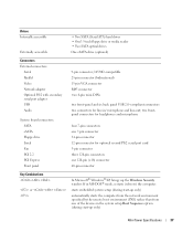
Mini Tower Computer Specifications Microprocessor Microprocessor type Internal cache Memory Type Memory connectors Memory modules supported Minimum memory Maximum memory BIOS address Computer Information Chipset Data bus ... 32 bits eight 24 32 Mb integrated network interface with ASF 1.03 and 2.0 support as defined by DMTF Capable of 10/100/1000 communication iAMT 3.0 Mini Tower Specifications 35
Mini Tower Computer Specifications Microprocessor Microprocessor type Internal cache Memory Type Memory connectors Memory modules supported Minimum memory Maximum memory BIOS address Computer Information Chipset Data bus ... 32 bits eight 24 32 Mb integrated network interface with ASF 1.03 and 2.0 support as defined by DMTF Capable of 10/100/1000 communication iAMT 3.0 Mini Tower Specifications 35
User's Guide
Page 36
... 10 W (x1) and 75 W (x16) maximum 36 pins (x1) and 164 pins (x16) one PCI Express lane (x1) and 16 PCI Express lanes (x16) 36 Mini Tower Specifications
... 10 W (x1) and 75 W (x16) maximum 36 pins (x1) and 164 pins (x16) one PCI Express lane (x1) and 16 PCI Express lanes (x16) 36 Mini Tower Specifications
User's Guide
Page 37
...PCI 2.2 PCI Express Front panel 9-pin connector; 16550C-compatible 25-pin connector (bidirectional) 15-pin VGA connector RJ45 connector two 6-pin mini-DINs two front-panel and six back panel USB 2.0-compliant connectors two connectors for optional second PS/2 serial port card 5-pin connector ... from one 120-pin (x16) connector 40-pin connector Key Combinations or In Microsoft® Windows® XP, brings up only) Mini Tower Specifications 37 two frontpanel connectors for headphones and microphone four 7-pin connectors one 7-pin connector 34-pin connector 12-pin connector for line-...
...PCI 2.2 PCI Express Front panel 9-pin connector; 16550C-compatible 25-pin connector (bidirectional) 15-pin VGA connector RJ45 connector two 6-pin mini-DINs two front-panel and six back panel USB 2.0-compliant connectors two connectors for optional second PS/2 serial port card 5-pin connector ... from one 120-pin (x16) connector 40-pin connector Key Combinations or In Microsoft® Windows® XP, brings up only) Mini Tower Specifications 37 two frontpanel connectors for headphones and microphone four 7-pin connectors one 7-pin connector 34-pin connector 12-pin connector for line-...


