
Quick Reference Guide
Page 24
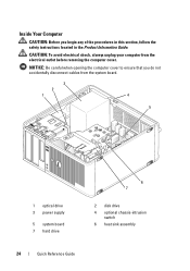
..., follow the safety instructions located in the Product Information Guide. CAUTION: To avoid electrical shock, always unplug your computer from the system board. 3 2 1 4 5 1 optical drive 3 power supply 5 system board 7 hard drive 6 7 2 disk drive 4 optional chassis-intrusion switch 6 heat sink assembly 24 Quick Reference Guide
..., follow the safety instructions located in the Product Information Guide. CAUTION: To avoid electrical shock, always unplug your computer from the system board. 3 2 1 4 5 1 optical drive 3 power supply 5 system board 7 hard drive 6 7 2 disk drive 4 optional chassis-intrusion switch 6 heat sink assembly 24 Quick Reference Guide
Quick Reference Guide
Page 34
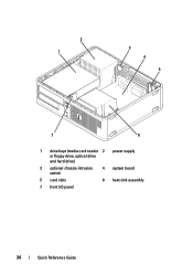
2 1 3 4 5 7 6 1 drive bays (media card reader 2 power supply or floppy drive, optical drive and hard drive) 3 optional chassis-intrusion switch 4 system board 5 card slots 6 heat sink assembly 7 front I/O panel 34 Quick Reference Guide
2 1 3 4 5 7 6 1 drive bays (media card reader 2 power supply or floppy drive, optical drive and hard drive) 3 optional chassis-intrusion switch 4 system board 5 card slots 6 heat sink assembly 7 front I/O panel 34 Quick Reference Guide
Quick Reference Guide
Page 45
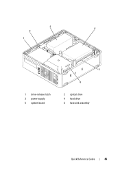
3 4 2 1 1 drive-release latch 3 power supply 5 system board 5 6 2 optical drive 4 hard drive 6 heat sink assembly Quick Reference Guide 45
3 4 2 1 1 drive-release latch 3 power supply 5 system board 5 6 2 optical drive 4 hard drive 6 heat sink assembly Quick Reference Guide 45
Quick Reference Guide
Page 65
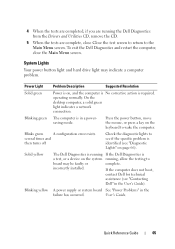
... completed, if you are running the Dell Diagnostics from the Drivers and Utilities CD, remove the CD. 5 When the tests are complete, close the Main Menu screen. Blinking yellow A power supply or system board See "Power Problems" in a powersaving mode. Power Light Problem Description Suggested Resolution Solid green Power is on the keyboard to board may...
... completed, if you are running the Dell Diagnostics from the Drivers and Utilities CD, remove the CD. 5 When the tests are complete, close the Main Menu screen. Blinking yellow A power supply or system board See "Power Problems" in a powersaving mode. Power Light Problem Description Suggested Resolution Solid green Power is on the keyboard to board may...
User's Guide
Page 4
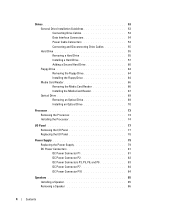
Drives 53 General Drive Installation Guidelines 53 Connecting Drive Cables 54 Data Interface Connectors 54 Power Cable Connectors 54 Connecting and Disconnecting Drive Cables 55 Hard Drive 55 Removing a Hard Drive 55 Installing a Hard Drive 57 Adding a ...Panel 77 Removing the I/O Panel 77 Replacing the I/O Panel 78 Power Supply 79 Replacing the Power Supply 79 DC Power Connectors 81 DC Power Connector P1 81 DC Power Connector P2 83 DC Power Connectors P3, P5, P8, and P9 83 DC Power Connector P7 84 DC Power Connector P10 84 Speakers 85 Installing a Speaker 85 Removing a ...
Drives 53 General Drive Installation Guidelines 53 Connecting Drive Cables 54 Data Interface Connectors 54 Power Cable Connectors 54 Connecting and Disconnecting Drive Cables 55 Hard Drive 55 Removing a Hard Drive 55 Installing a Hard Drive 57 Adding a ...Panel 77 Removing the I/O Panel 77 Replacing the I/O Panel 78 Power Supply 79 Replacing the Power Supply 79 DC Power Connectors 81 DC Power Connector P1 81 DC Power Connector P2 83 DC Power Connectors P3, P5, P8, and P9 83 DC Power Connector P7 84 DC Power Connector P10 84 Speakers 85 Installing a Speaker 85 Removing a ...
User's Guide
Page 6
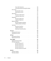
Power Cable Connectors 128 Connecting and Disconnecting Drive Cables 129 Drive Inserts 129 Removing Drive Inserts 129 Replacing Drive Inserts 131 Optical Drive 131 Removing an ... the Processor 150 I/O Panel 153 Removing the I/O Panel 153 Replacing the I/O Panel 154 Power Supply 155 Replacing the Power Supply 155 DC Power Connectors 157 DC Power Connector P1 157 DC Power Connector P2 159 DC Power Connector P3 160 DC Power Connector P4 160 DC Power Connector P5 and P6 160 Speakers 163 Installing a Speaker 163 Removing a Speaker 164...
Power Cable Connectors 128 Connecting and Disconnecting Drive Cables 129 Drive Inserts 129 Removing Drive Inserts 129 Replacing Drive Inserts 131 Optical Drive 131 Removing an ... the Processor 150 I/O Panel 153 Removing the I/O Panel 153 Replacing the I/O Panel 154 Power Supply 155 Replacing the Power Supply 155 DC Power Connectors 157 DC Power Connector P1 157 DC Power Connector P2 159 DC Power Connector P3 160 DC Power Connector P4 160 DC Power Connector P5 and P6 160 Speakers 163 Installing a Speaker 163 Removing a Speaker 164...
User's Guide
Page 14
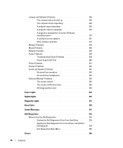
... solid blue screen appears 337 Other software problems 337 Memory Problems 338 Mouse Problems 338 Network Problems 339 Power Problems 339 Troubleshooting Power Problems 339 Power Supply Self-Test 340 Printer Problems 341 Scanner Problems 342 Sound and Speaker Problems 342 No sound from speakers ... quality is poor 344 Power Lights 344 System Lights 345 Diagnostic Lights 347 Beep Codes 350 System Messages 351 Dell Diagnostics 353 When to Use the Dell Diagnostics 353 Starting the Dell Diagnostics From Your Hard Drive . . . . . 353 Starting the Dell Diagnostics From the Drivers ...
... solid blue screen appears 337 Other software problems 337 Memory Problems 338 Mouse Problems 338 Network Problems 339 Power Problems 339 Troubleshooting Power Problems 339 Power Supply Self-Test 340 Printer Problems 341 Scanner Problems 342 Sound and Speaker Problems 342 No sound from speakers ... quality is poor 344 Power Lights 344 System Lights 345 Diagnostic Lights 347 Beep Codes 350 System Messages 351 Dell Diagnostics 353 When to Use the Dell Diagnostics 353 Starting the Dell Diagnostics From Your Hard Drive . . . . . 353 Starting the Dell Diagnostics From the Drivers ...
User's Guide
Page 29
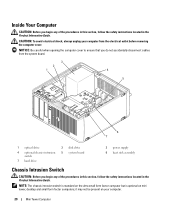
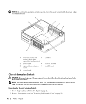
... form factor computer but is optional on your computer from the system board. 3 2 1 4 5 6 7 1 optical drive 4 optional chassis-intrusion switch 7 hard drive 2 disk drive 5 system board 3 power supply 6 heat sink assembly Chassis Intrusion Switch CAUTION: Before you do not accidentally disconnect cables from the electrical outlet before removing the computer cover. it may...
... form factor computer but is optional on your computer from the system board. 3 2 1 4 5 6 7 1 optical drive 4 optional chassis-intrusion switch 7 hard drive 2 disk drive 5 system board 3 power supply 6 heat sink assembly Chassis Intrusion Switch CAUTION: Before you do not accidentally disconnect cables from the electrical outlet before removing the computer cover. it may...
User's Guide
Page 38
... light (on the system board Power DC power supply: Wattage Heat dissipation Voltage Backup battery NOTE: Power consumption from an AC power source can be zero when the computer is unplugged from the AC power source. 305 W 1041 BTU/hr NOTE: Heat dissipation is not drawing power from that power source. manual selection power supplies-90 to 135 V at 60...
... light (on the system board Power DC power supply: Wattage Heat dissipation Voltage Backup battery NOTE: Power consumption from an AC power source can be zero when the computer is unplugged from the AC power source. 305 W 1041 BTU/hr NOTE: Heat dissipation is not drawing power from that power source. manual selection power supplies-90 to 135 V at 60...
User's Guide
Page 79
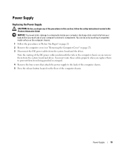
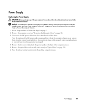
...the computer chassis as you replace them to prevent them from being pinched or crimped. 4 Remove the four screws that attach the power supply to components inside your computer, discharge static electricity from the system board and the drives. NOTICE: To prevent static damage to the... back of the computer chassis. 5 Press the release button located on page 27). 3 Disconnect the DC power cables from your computer's electronic components. Power Supply Replacing the Power Supply CAUTION: Before you begin any of your body before you touch any of the procedures in this section, follow...
...the computer chassis as you replace them to prevent them from being pinched or crimped. 4 Remove the four screws that attach the power supply to components inside your computer, discharge static electricity from the system board and the drives. NOTICE: To prevent static damage to the... back of the computer chassis. 5 Press the release button located on page 27). 3 Disconnect the DC power cables from your computer's electronic components. Power Supply Replacing the Power Supply CAUTION: Before you begin any of your body before you touch any of the procedures in this section, follow...
User's Guide
Page 80
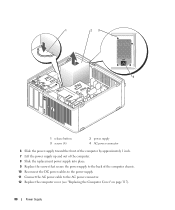
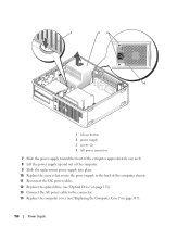
1 23 4 1 release button 3 screws (4) 2 power supply 4 AC power connector 6 Slide the power supply toward the front of the computer by approximately 1 inch. 7 Lift the power supply up and out of the computer. 8 Slide the replacement power supply into place. 9 Replace the screws that secure the power supply to the back of the computer chassis. 10 Reconnect the DC power cables to the power supply. 11 Connect the AC power cable to the AC power connector. 12 Replace the computer cover (see "Replacing the Computer Cover" on page 317). 80 Power Supply
1 23 4 1 release button 3 screws (4) 2 power supply 4 AC power connector 6 Slide the power supply toward the front of the computer by approximately 1 inch. 7 Lift the power supply up and out of the computer. 8 Slide the replacement power supply into place. 9 Replace the screws that secure the power supply to the back of the computer chassis. 10 Reconnect the DC power cables to the power supply. 11 Connect the AC power cable to the AC power connector. 12 Replace the computer cover (see "Replacing the Computer Cover" on page 317). 80 Power Supply
User's Guide
Page 81
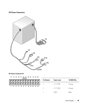
DC Power Connectors DC Power Connector P1 13 14 15 16 17 18 19 20 21 22 23 24 1 2 3 4 5 6 7 8 9 10 11 12 Pin Number 1 2 3 Signal name +3.3 VDC +3.3 VDC GND 18-AWG Wire Orange Orange Black Power Supply 81
DC Power Connectors DC Power Connector P1 13 14 15 16 17 18 19 20 21 22 23 24 1 2 3 4 5 6 7 8 9 10 11 12 Pin Number 1 2 3 Signal name +3.3 VDC +3.3 VDC GND 18-AWG Wire Orange Orange Black Power Supply 81
User's Guide
Page 82
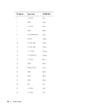
Pin Number 4 5 6 7 8 9 10 11 12 13 14 15 16 17 18 19 20 21 22 Signal name +5 VDC GND +5 VDC GND PS_PWRGOOD P5AUX V_12P0_DIG V_12P0_DIG +3.3 VDC +3.3VDC/SE* -12 VDC GND PWR_PS_ON GND GND GND NC +5 VDC +5 VDC 18-AWG Wire Red Black Red Black Gray Purple White White Orange Orange Blue Black Green Black Black Black NC Red Red 82 Power Supply
Pin Number 4 5 6 7 8 9 10 11 12 13 14 15 16 17 18 19 20 21 22 Signal name +5 VDC GND +5 VDC GND PS_PWRGOOD P5AUX V_12P0_DIG V_12P0_DIG +3.3 VDC +3.3VDC/SE* -12 VDC GND PWR_PS_ON GND GND GND NC +5 VDC +5 VDC 18-AWG Wire Red Black Red Black Gray Purple White White Orange Orange Blue Black Green Black Black Black NC Red Red 82 Power Supply
User's Guide
Page 83
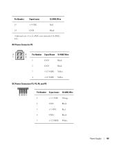
Use 22-AWG wire instead of 18-AWG wire. DC Power Connector P2 3 4 Pin Number Signal Name 18-AWG Wire 1 2 1 GND Black 2 GND Black 3 +12 VADC Yellow 4 +12 VADC Yellow DC Power Connectors P3, P5, P8, and P9 Pin Number Signal name 18-AWG Wire 1 +3.3 VDC Orange 2 GND Black 3 +5 VDC Red 4 GND Black 5 +12 VBDC White Power Supply 83 Pin Number Signal name 18-AWG Wire 23 +5 VDC Red 24 GND Black *Optional wire.
Use 22-AWG wire instead of 18-AWG wire. DC Power Connector P2 3 4 Pin Number Signal Name 18-AWG Wire 1 2 1 GND Black 2 GND Black 3 +12 VADC Yellow 4 +12 VADC Yellow DC Power Connectors P3, P5, P8, and P9 Pin Number Signal name 18-AWG Wire 1 +3.3 VDC Orange 2 GND Black 3 +5 VDC Red 4 GND Black 5 +12 VBDC White Power Supply 83 Pin Number Signal name 18-AWG Wire 23 +5 VDC Red 24 GND Black *Optional wire.
User's Guide
Page 84
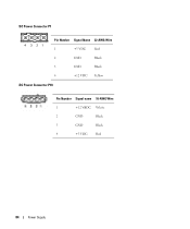
DC Power Connector P7 4 321 Pin Number Signal Name 22-AWG Wire 1 +5 VDC Red 2 GND Black 3 GND Black 4 +12 VDC Yellow DC Power Connector P10 Pin Number Signal name 18-AWG Wire 1 +12 VBDC White 2 GND Black 3 GND Black 4 +5 VDC Red 84 Power Supply
DC Power Connector P7 4 321 Pin Number Signal Name 22-AWG Wire 1 +5 VDC Red 2 GND Black 3 GND Black 4 +12 VDC Yellow DC Power Connector P10 Pin Number Signal name 18-AWG Wire 1 +12 VBDC White 2 GND Black 3 GND Black 4 +5 VDC Red 84 Power Supply
User's Guide
Page 92
... you do not accidentally disconnect cables from the system board. 2 1 3 4 5 7 6 1 drive bays (media card 5 card slots reader or floppy drive, optical drive and hard drive) 2 power supply 6 heat sink assembly 3 optional chassis-intrusion 7 front I/O panel switch 4 system board Chassis Intrusion Switch CAUTION: Before you begin any of the procedures in this section...
... you do not accidentally disconnect cables from the system board. 2 1 3 4 5 7 6 1 drive bays (media card 5 card slots reader or floppy drive, optical drive and hard drive) 2 power supply 6 heat sink assembly 3 optional chassis-intrusion 7 front I/O panel switch 4 system board Chassis Intrusion Switch CAUTION: Before you begin any of the procedures in this section...
User's Guide
Page 101
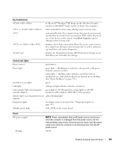
... panel (See "Diagnostic Lights" on page 347.) Standby power light AUX_PWR on the system board Power DC power supply: Wattage NOTE: Power consumption from an AC power source can be zero when the computer is unplugged from the AC power source. 280 W Desktop Computer Specifications 101 blinking green indicates... from the network environment specified by the remote boot environment (PXE) rather than from one of power from the power supply even when the computer is not drawing power from that power source, but the internal battery does draw a minute amount of the devices in MS-DOS®...
... panel (See "Diagnostic Lights" on page 347.) Standby power light AUX_PWR on the system board Power DC power supply: Wattage NOTE: Power consumption from an AC power source can be zero when the computer is unplugged from the AC power source. 280 W Desktop Computer Specifications 101 blinking green indicates... from the network environment specified by the remote boot environment (PXE) rather than from one of power from the power supply even when the computer is not drawing power from that power source, but the internal battery does draw a minute amount of the devices in MS-DOS®...
User's Guide
Page 102
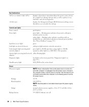
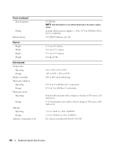
manual selection power supplies - 90 to 135 V at 50/60 Hz; 180 to 265 V at 50/60 Hz 3-V CR2032 lithium coin cell 11.4 cm (4.5 inches) 39.9 cm (15.7 inches) ...,000 ft) -15.2 to 10,668 m (-50 to 35,000 ft) G2 or lower as defined by ISA-S71.04-1985 102 Desktop Computer Specifications Power (continued) Heat dissipation Voltage Backup battery Physical Height Width Depth Weight Environmental Temperature: Operating Storage Relative humidity Maximum vibration: Operating Storage Maximum shock: Operating Storage...
manual selection power supplies - 90 to 135 V at 50/60 Hz; 180 to 265 V at 50/60 Hz 3-V CR2032 lithium coin cell 11.4 cm (4.5 inches) 39.9 cm (15.7 inches) ...,000 ft) -15.2 to 10,668 m (-50 to 35,000 ft) G2 or lower as defined by ISA-S71.04-1985 102 Desktop Computer Specifications Power (continued) Heat dissipation Voltage Backup battery Physical Height Width Depth Weight Environmental Temperature: Operating Storage Relative humidity Maximum vibration: Operating Storage Maximum shock: Operating Storage...
User's Guide
Page 155
... to prevent them from your body before you remove them from being pinched or crimped. 4 Remove the two screws that attach the power supply to components inside your computer's electronic components. You can do so by touching an unpainted metal surface on the computer chassis. 1 ...Follow the procedures in the Product Information Guide. Power Supply 155 NOTICE: To prevent static damage to the back of the computer chassis. 5 Remove the optical drive and carefully set it aside (...
... to prevent them from your body before you remove them from being pinched or crimped. 4 Remove the two screws that attach the power supply to components inside your computer's electronic components. You can do so by touching an unpainted metal surface on the computer chassis. 1 ...Follow the procedures in the Product Information Guide. Power Supply 155 NOTICE: To prevent static damage to the back of the computer chassis. 5 Remove the optical drive and carefully set it aside (...
User's Guide
Page 156
1 23 4 1 release button 2 power supply 3 screws (2) 4 AC power connector 7 Slide the power supply toward the front of the computer approximately one inch. 8 Lift the power supply up and out of the computer. 9 Slide the replacement power supply into place. 10 Replace the screws that secure the power supply to the back of the computer chassis. 11 Reconnect the DC power cables. 12 Replace the optical drive (see "Optical Drive" on page 131). 13 Connect the AC power cable to the connector. 14 Replace the computer cover (see "Replacing the Computer Cover" on page 317). 156 Power Supply
1 23 4 1 release button 2 power supply 3 screws (2) 4 AC power connector 7 Slide the power supply toward the front of the computer approximately one inch. 8 Lift the power supply up and out of the computer. 9 Slide the replacement power supply into place. 10 Replace the screws that secure the power supply to the back of the computer chassis. 11 Reconnect the DC power cables. 12 Replace the optical drive (see "Optical Drive" on page 131). 13 Connect the AC power cable to the connector. 14 Replace the computer cover (see "Replacing the Computer Cover" on page 317). 156 Power Supply


