
Dell OptiPlex 755 Support Question
Dell OptiPlex 755 Support Question
Find answers below for this question about Dell OptiPlex 755.Need a Dell OptiPlex 755 manual? We have 3 online manuals for this item!
Question posted by Deeust on April 27th, 2014
How To Install Power Supply For Optiplex 755
The person who posted this question about this Dell product did not include a detailed explanation. Please use the "Request More Information" button to the right if more details would help you to answer this question.
Current Answers
Related Dell OptiPlex 755 Manual Pages
Quick Reference
Guide - Page 65
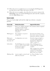
... may be faulty or
complete.
On the desktop computer, a solid green light indicates a network connection.
Press the power button, move the mouse, or press a key on page 66). Quick Reference Guide
65
Blinking yellow A power supply or system board See "Power Problems" in a powersaving mode. Blinks green
A configuration error exists. incorrectly installed. 4 When the tests are...
User's Guide - Page 4
... 74
I/O Panel 77 Removing the I/O Panel 77 Replacing the I/O Panel 78
Power Supply 79 Replacing the Power Supply 79 DC Power Connectors 81 DC Power Connector P1 81 DC Power Connector P2 83 DC Power Connectors P3, P5, P8, and P9 83 DC Power Connector P7 84 DC Power Connector P10 84
Speakers 85 Installing a Speaker 85 Removing a Speaker 86
4
Contents
User's Guide - Page 6
... 146
Processor 149 Removing the Processor 149 Installing the Processor 150
I/O Panel 153 Removing the I/O Panel 153 Replacing the I/O Panel 154
Power Supply 155 Replacing the Power Supply 155 DC Power Connectors 157 DC Power Connector P1 157 DC Power Connector P2 159 DC Power Connector P3 160 DC Power Connector P4 160 DC Power Connector P5 and P6 160
Speakers...
User's Guide - Page 29
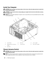
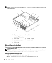
...6 7
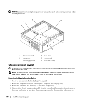
1 optical drive
4 optional chassis-intrusion switch
7 hard drive
2 disk drive 5 system board
3 power supply 6 heat sink assembly
Chassis Intrusion Switch
CAUTION: Before you begin any of the procedures in this section, follow... removing the computer cover. it may not be present on mini tower, desktop and small form factor computers;
Inside Your Computer
CAUTION: Before you begin ...
User's Guide - Page 38
... amber indicates a problem with an installed device; solid amber indicates an internal power problem (See "Power Problems" on page 339.)
hard drive...Extension settings screen that power source. blinking green indicates sleep mode; solid green indicates power-on the system board
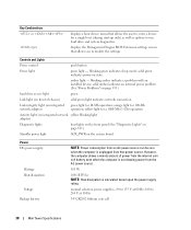
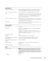
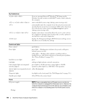
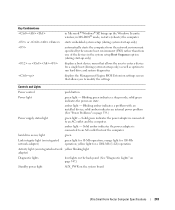
Power DC power supply:
Wattage Heat dissipation
Voltage Backup battery
NOTE: Power consumption from that allows...
User's Guide - Page 92
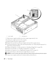
... is optional on mini tower, desktop, and small form factor computers; NOTICE: Be careful when opening the computer cover to ensure that you do not accidentally disconnect cables from the system board.
2
1
3
4
5
7
6
1 drive bays (media card
5 card slots
reader or floppy drive,
optical drive and hard drive)
2 power supply
6 heat sink assembly
3 optional...
User's Guide - Page 101
... power light
AUX_PWR on state. blinking amber indicates a problem with an installed...power from the power supply even when the computer is not drawing power from one of the devices in Microsoft® Windows® XP, brings up only)
automatically starts the computer from the network environment specified by the remote boot environment (PXE) rather than from the AC power source.
280 W
Desktop...
User's Guide - Page 102
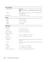
... Maximum shock: Operating
Storage
Altitude: Operating Storage
Airborne contaminant level
955 BTU/hr NOTE: Heat dissipation is calculated based upon the power supply rating. manual selection power supplies - 90 to 135 V at 50/60 Hz; 180 to 265 V at 50/60 Hz 3-V CR2032 lithium coin cell
...10,668 m (-50 to 35,000 ft) G2 or lower as defined by ISA-S71.04-1985
102
Desktop Computer Specifications
User's Guide - Page 170
... that you do not accidentally disconnect cables from the system board.
3
4
2
1
5 6
1 drive-release latch 2 optical drive 3 power supply and fan
4 hard drive 5 system board 6 heat sink assembly
Chassis Intrusion Switch
CAUTION: Before you begin any of the procedures in this ...
170
Small Form Factor Computer it may not be present on mini tower, desktop, and small form factor computers;
User's Guide - Page 178
...power source. solid green indicates power-on the system board
Power DC power supply:
Wattage
NOTE: Power consumption from an AC power source can be zero when the computer is not drawing power...user to modify the settings
Controls and Lights
Power control
push button
Power light
green light -
blinking amber indicates a problem with an installed device; orange light for a single boot (...
User's Guide - Page 219

... the Computer Cover" on page 168). 3 If installed, remove the optical drive (see "Removing an Optical Drive" on page 204). 4 If installed, remove the floppy drive or media card reader ... Remove the three screws that attach the power supply to components inside your computer's electronic components.
Power Supply
219 Power Supply
Replacing the Power Supply
CAUTION: Before you begin any of the ...
User's Guide - Page 220
... drives (see "System Board Components" on
page 172 for connector locations). 12 Replace the floppy drive or media card reader (see "Installing a Floppy Drive" on page 208). 13 Replace the optical drive (see "Installing an Optical Drive" on page 205). 14 Replace the computer cover (see "Replacing the Computer Cover" on .
220
Power Supply
User's Guide - Page 221
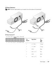
DC Power Connectors
NOTE: The power supply installed in your computer is one of two options as illustrated below. DC Power Connector P1 13 14 15 16 17 18 19 20 21 22 23 24
1 2 3 4 5 6 7 8 9 10 11 12
Pin Number
Signal Name
1
+3.3 VDC
2
+3.3 VDC
3
GND
4
VCC (+5 V)
5
GND
6
VCC (+5 V)
18AWG Wire
Orange
Orange
Black
Red
Black
Red
Power Supply
221
User's Guide - Page 243
...boot (during start-up the Windows Security window; solid amber indicates an internal power problem (See "Power Problems" on state. hard drive access light
green
Link integrity light (on... amber indicates a problem with an installed device;
orange light for 100-Mb operation; solid green indicates the power-on page 339.)
Power supply status light
green light -
Key ...
User's Guide - Page 249

... the new drive and skip to step 9.
1
2
3
1 drive 2 drive rails (2) 3 screws (4)
2 If you are installing a new drive, rather than replacing an already installed drive, attach the plastic drive rails-located inside your computer, discharge static electricity from the power supply before removing the hard drive. NOTICE: To avoid damage to keep, back up and...
User's Guide - Page 267

Power Supply
267
NOTICE: To prevent static damage to components inside your computer, discharge static electricity ... so by touching an unpainted metal surface on the computer chassis. 1 Follow the procedures in the Product Information Guide. Speakers
Installing a Speaker
CAUTION: Before you touch any of the procedures in this section, follow the safety instructions located in "Before You...
User's Guide - Page 269
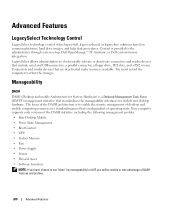
... are deactivated make resources available. The focus of the DASH initiative including the following management profiles: • Base Desktop Mobile • Power State Management • Boot Control • CPU • System Memory • Fan • Power Supply • Sensor • Physical Asset • Software Inventory
NOTE: If you have chosen to use "None" (no...
User's Guide - Page 272

...™ applications and Dell™ Client Manager (DCM) are available on some computers) installed and enabled has been opened or the chassis intrusion alert has been cleared.
For more ...down .
RMCP messages can manage your system management needs. The standard is too hot and the power supply has shut down , or restart. Your computer supports the following ASF version 1.03 and 2.0...
User's Guide - Page 340
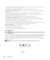
... to the same electrical outlet
Power Supply Self-Test
. If your mini tower, desktop, or small form factor computer has been certified for your computer).
• Perform the power supply self-test, if applicable (see "Power Supply Self-Test" on page 340). NOTE: The power supply self-test feature is available only with the power supply connected to computer devices or...
User's Guide - Page 341
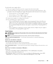
... View installed printers or fax printers. 2 If the printer is identified. If the test LED illuminates, the power supply is defective. Replace the defective device/part or contact Dell (see "Power Supply" on... any of your computer:
• For the mini tower, see "Power Supply" on page 79
• For the desktop, see "Power Supply" on page 155 • For the small form factor, see "...
Similar Questions


How To Reset Power On Optiplex 755 Small Form Factor
(Posted by akin1Un 10 years ago)

Optiplex 960 Will Not Boot After Installing Power Supply And Systemboard
(Posted by macPa 10 years ago)
