
Dell OptiPlex 755 Support Question
Dell OptiPlex 755 Support Question
Find answers below for this question about Dell OptiPlex 755.Need a Dell OptiPlex 755 manual? We have 3 online manuals for this item!
Question posted by rajo on July 23rd, 2013
How To Remove Power Supply From Dell Optiplex 755
The person who posted this question about this Dell product did not include a detailed explanation. Please use the "Request More Information" button to the right if more details would help you to answer this question.
Current Answers
Related Dell OptiPlex 755 Manual Pages
Quick Reference
Guide - Page 6
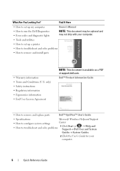
... Information Guide
• How to remove and replace parts
Dell™ OptiPlex™ User's Guide
• Specifications
Microsoft Windows Help and Support
• How to configure system settings
Center
• How to remove and install parts
• Warranty information • Terms and Conditions (U.S. What Are You Looking For? Find It Here
• How to...
Quick Reference
Guide - Page 24
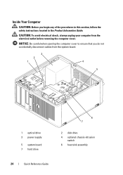
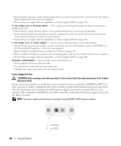
..., follow the safety instructions located in the Product Information Guide.
CAUTION: To avoid electrical shock, always unplug your computer from the system board.
3
2
1
4
5
1 optical drive 3 power supply
5 system board 7 hard drive
6 7
2 disk drive 4 optional chassis-intrusion
switch 6 heat sink assembly
24
Quick Reference Guide
Inside Your Computer
CAUTION: Before you do not...
Quick Reference
Guide - Page 65
... light may be faulty or
complete.
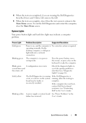
On the desktop computer, a solid green light indicates a network connection. Power Light
Problem Description
Suggested Resolution
Solid green
Power is on page 66).
4 When the tests are completed, if you are running the Dell Diagnostics from the Drivers and Utilities CD, remove the CD.
5 When the tests are complete...
User's Guide - Page 4
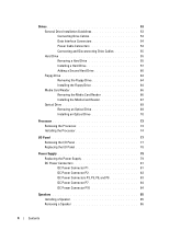
... Processor 73 Installing the Processor 74
I/O Panel 77 Removing the I/O Panel 77 Replacing the I/O Panel 78
Power Supply 79 Replacing the Power Supply 79 DC Power Connectors 81 DC Power Connector P1 81 DC Power Connector P2 83 DC Power Connectors P3, P5, P8, and P9 83 DC Power Connector P7 84 DC Power Connector P10 84
Speakers 85 Installing a Speaker...
User's Guide - Page 6
... Hard Drive 146
Processor 149 Removing the Processor 149 Installing the Processor 150
I/O Panel 153 Removing the I/O Panel 153 Replacing the I/O Panel 154
Power Supply 155 Replacing the Power Supply 155 DC Power Connectors 157 DC Power Connector P1 157 DC Power Connector P2 159 DC Power Connector P3 160 DC Power Connector P4 160 DC Power Connector P5 and P6 160...
User's Guide - Page 14
... 338 Mouse Problems 338 Network Problems 339 Power Problems 339
Troubleshooting Power Problems 339 Power Supply Self-Test 340 Printer Problems 341 Scanner...Power Lights 344
System Lights 345
Diagnostic Lights 347
Beep Codes 350
System Messages 351
Dell Diagnostics 353 When to Use the Dell Diagnostics 353 Starting the Dell Diagnostics From Your Hard Drive . . . . . 353 Starting the Dell...
User's Guide - Page 18
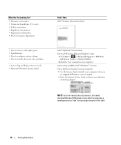
...Express Service Code • Microsoft Windows License Label
Find It Here Dell™ Product Information Guide
Dell™ OptiPlex™ User's Guide Microsoft Windows Help and Support Center
1 Click Start or &#... information • End User License Agreement
• How to remove and replace parts • Specifications • How to configure system settings • How to discourage...
User's Guide - Page 29
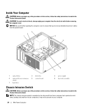
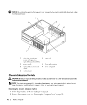
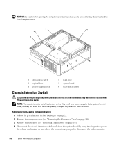
... cables from the electrical outlet before removing the computer cover. NOTE: The chassis intrusion switch is standard on the ultra small form factor computer but is optional on your computer from the system board.
3
2
1
4
5
6 7
1 optical drive
4 optional chassis-intrusion switch
7 hard drive
2 disk drive 5 system board
3 power supply 6 heat sink assembly
Chassis Intrusion...
User's Guide - Page 79
... the floor of the procedures in this section, follow the safety instructions located in the computer chassis as you remove them from being pinched or crimped.
4 Remove the four screws that attach the power supply to components inside your computer, discharge static electricity from the system board and the drives. You must route these...
User's Guide - Page 92
... drive)
2 power supply
6 heat sink assembly
3 optional chassis-intrusion 7 front I/O panel switch
4 system board
Chassis Intrusion Switch
CAUTION: Before you begin any of the procedures in this section, follow the safety instructions located in "Before You Begin" on page 21. 2 Remove the computer cover (see "Removing the Computer Cover" on page 90).
92
Desktop Computer...
User's Guide - Page 101
... to run hard drive and system diagnostics
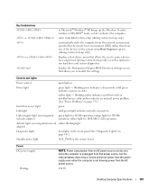
displays the Management Engine BIOS Extension settings screen that power source, but the internal battery does draw a minute amount of power from the power supply even when the computer is unplugged from the AC power source.
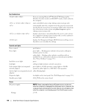
280 W
Desktop Computer Specifications
101 blinking amber indicates a problem with an installed device;
User's Guide - Page 102
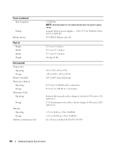
... Maximum shock: Operating
Storage
Altitude: Operating Storage
Airborne contaminant level
955 BTU/hr NOTE: Heat dissipation is calculated based upon the power supply rating. manual selection power supplies - 90 to 135 V at 50/60 Hz; 180 to 265 V at 50/60 Hz 3-V CR2032 lithium coin cell
...10,668 m (-50 to 35,000 ft) G2 or lower as defined by ISA-S71.04-1985
102
Desktop Computer Specifications
User's Guide - Page 155
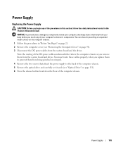
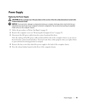
... on page 90). 3 Disconnect the DC power cables from being pinched or crimped.
4 Remove the two screws that attach the power supply to the back of the computer chassis. Note the routing of the DC power cables underneath the tabs in the Product Information Guide.
Power Supply
155 Power Supply
Replacing the Power Supply
CAUTION: Before you begin any of the...
User's Guide - Page 170
...21. 2 Remove the computer cover (see "Removing the Computer Cover" on page 168). 3 Remove the hard drive (see "Removing a Hard Drive" on page 197). 4 Disconnect the chassis intrusion switch cable from the system board.
3
4
2
1
5 6
1 drive-release latch 2 optical drive 3 power supply and fan
4... form factor computer but is optional on mini tower, desktop, and small form factor computers;
User's Guide - Page 178
... solid green indicates power-on the system board
Power DC power supply:
Wattage
NOTE: Power consumption from an AC power source can be zero when the computer is not drawing power from the AC power source.
275 ...Diagnostic lights
four lights on the front panel (See "Dell Diagnostics" on page 353.)
Standby power light
AUX_PWR on state. Key Combinations
or
or
If you to modify...
User's Guide - Page 219

... any of the procedures in this section, follow the safety instructions located in the computer frame as you remove them to prevent their being pinched or crimped. 6 Remove the three screws that attach the power supply to components inside your computer's electronic components. You must route these cables properly when you replace them from...
User's Guide - Page 269
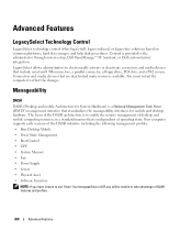
... following management profiles: • Base Desktop Mobile • Power State Management • Boot Control • CPU • System Memory • Fan • Power Supply • Sensor • Physical Asset...procedures. Control is to the administrator through system setup, Dell OpenManage™ IT Assistant, or Dell custom-factory integration. The focus of the DASH architecture ...
User's Guide - Page 340
... the AC power at your computer). • Remove and then reinstall all memory modules (see
the "System Board Components" section for ENERGY STAR® 4.0, then your power supply is receiving electrical power, but an internal power problem may be performed with ENERGY STAR 4.0 power supplies.
340
Solving Problems
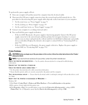
1
2
1 test button 2 test LED If your mini tower, desktop, or small...
User's Guide - Page 341
... (Printer Port). NOTE: If you begin any of your computer:
• For the mini tower, see "Power Supply" on page 79
• For the desktop, see "Power Supply" on page 155 • For the small form factor, see "Contacting Dell" on page 370).
- For a parallel printer, ensure that the Print to the printer and the computer...
User's Guide - Page 373
...consult a representative of the FCC Rules. Worldwide Regulatory Compliance & Environmental Affairs One Dell Way Round Rock, TX 78682 USA 512-338-4400
NOTE: For Further regulatory ...with the FCC regulations:
• Product name: Dell™ OptiPlex™ 755
• Model numbers: DCTR, DCNE, DCSM, DCCY
• Company name: Dell Inc. FCC Notices (U.S. or an experienced radio/television...
Similar Questions


How To Remove Power Supply From Dell Inspiron 660s
I can't find a way to take out the old power supply in my Inspiron 660s. It's loose but there I no r...
I can't find a way to take out the old power supply in my Inspiron 660s. It's loose but there I no r...
(Posted by sfishesfish 10 years ago)

How To Reset Power On Optiplex 755 Small Form Factor
(Posted by akin1Un 10 years ago)