

Quick Reference Guide
Page 13
Unless otherwise noted, each procedure assumes that the following tools: • Small flat-blade screwdriver • Phillips screwdriver • Flash BIOS update program floppy disk or CD Turning Off Your Computer NOTICE: To avoid losing data, save and close all open files and exit all ...steps in "Turning Off Your Computer" on page 13 and "Mini Tower Computer" on page 16. • You have read the safety information in your Dell™ Product Information Guide. • A component can be replaced by performing the removal procedure in the lower-right corner of the desktop, click the arrow...
Unless otherwise noted, each procedure assumes that the following tools: • Small flat-blade screwdriver • Phillips screwdriver • Flash BIOS update program floppy disk or CD Turning Off Your Computer NOTICE: To avoid losing data, save and close all open files and exit all ...steps in "Turning Off Your Computer" on page 13 and "Mini Tower Computer" on page 16. • You have read the safety information in your Dell™ Product Information Guide. • A component can be replaced by performing the removal procedure in the lower-right corner of the desktop, click the arrow...
Quick Reference Guide
Page 66
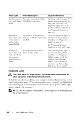
...the specific problem is identified (see "Diagnostic Lights" on page 66). To help to card may be faulty or incorrectly see "Contacting Dell" in the User's Guide. Power Light Problem Description Suggested Resolution Solid green and a A problem was detected while beep code during ... the graphics Check the diagnostic lights to identify the problem. identified (see "Diagnostic Lights" on page 66). no video during the BIOS was executing. Also, check the diagnostic lights to the operating system. 66 Quick Reference Guide NOTE: After the computer completes POST, ...
...the specific problem is identified (see "Diagnostic Lights" on page 66). To help to card may be faulty or incorrectly see "Contacting Dell" in the User's Guide. Power Light Problem Description Suggested Resolution Solid green and a A problem was detected while beep code during ... the graphics Check the diagnostic lights to identify the problem. identified (see "Diagnostic Lights" on page 66). no video during the BIOS was executing. Also, check the diagnostic lights to the operating system. 66 Quick Reference Guide NOTE: After the computer completes POST, ...
Quick Reference Guide
Page 67
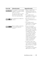
...working electrical outlet (see "Power Problems" in the User's Guide). • If the problem persists, contact Dell (see "Contacting Dell" in a normal off condition or a possible pre-BIOS failure has occurred. If the computer starts normally, continue to the operating system. • Plug the computer ...into a working memory of the same type into your system). • If the problem persists, contact Dell (see "Installing Memory" in...
...working electrical outlet (see "Power Problems" in the User's Guide). • If the problem persists, contact Dell (see "Contacting Dell" in a normal off condition or a possible pre-BIOS failure has occurred. If the computer starts normally, continue to the operating system. • Plug the computer ...into a working memory of the same type into your system). • If the problem persists, contact Dell (see "Installing Memory" in...
Quick Reference Guide
Page 71
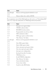
... 0FFFFh If you experience any of the following beep code errors, see "Contacting Dell" in the User's Guide for video ROM failure Quick Reference Guide 71 Code 1-3-1 through 2-4-4 3-1-1 3-1-2 3-1-3 3-1-4 3-2-2 3-2-4 3-3-1 3-3-2 3-3-4 3-4-1 3-4-2 3-4-3 Cause Microprocessor register failure NVRAM read/write failure ROM BIOS checksum failure Programmable interval timer failure DMA initialization failure DMA page register read/write...
... 0FFFFh If you experience any of the following beep code errors, see "Contacting Dell" in the User's Guide for video ROM failure Quick Reference Guide 71 Code 1-3-1 through 2-4-4 3-1-1 3-1-2 3-1-3 3-1-4 3-2-2 3-2-4 3-3-1 3-3-2 3-3-4 3-4-1 3-4-2 3-4-3 Cause Microprocessor register failure NVRAM read/write failure ROM BIOS checksum failure Programmable interval timer failure DMA initialization failure DMA page register read/write...
User's Guide
Page 21
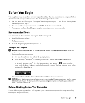
... Your Computer" on page 21 and "Before Working Inside Your Computer" on page 21. • You have read the safety information in your Dell™ Product Information Guide. • A component can be replaced by performing the removal procedure in your operating system, press and hold the power...process is complete. Before Working Inside Your Computer Use the following tools: • Small flat-blade screwdriver • Phillips screwdriver • Flash BIOS update program floppy disk or CD Turning Off Your Computer NOTICE: To avoid losing data, save and close all open files and exit all ...
... Your Computer" on page 21 and "Before Working Inside Your Computer" on page 21. • You have read the safety information in your Dell™ Product Information Guide. • A component can be replaced by performing the removal procedure in your operating system, press and hold the power...process is complete. Before Working Inside Your Computer Use the following tools: • Small flat-blade screwdriver • Phillips screwdriver • Flash BIOS update program floppy disk or CD Turning Off Your Computer NOTICE: To avoid losing data, save and close all open files and exit all ...
User's Guide
Page 31
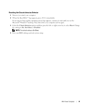
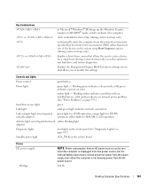
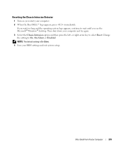
Resetting the Chassis Intrusion Detector 1 Turn on (or restart) your BIOS settings and exit system setup. or right-arrow key to On, On-Silent, or Disabled. Change the setting to select Reset. NOTE: The default setting is On-Silent. 4 Save your computer. 2 When the blue DELL™ logo appears, press immediately. Mini Tower Computer 31 Then shut down your computer and try again. 3 Select the Chassis Intrusion option and then press the left- If you wait too long and the operating system logo appears, continue to wait until you see the Microsoft® Windows® desktop.
Resetting the Chassis Intrusion Detector 1 Turn on (or restart) your BIOS settings and exit system setup. or right-arrow key to On, On-Silent, or Disabled. Change the setting to select Reset. NOTE: The default setting is On-Silent. 4 Save your computer. 2 When the blue DELL™ logo appears, press immediately. Mini Tower Computer 31 Then shut down your computer and try again. 3 Select the Chassis Intrusion option and then press the left- If you wait too long and the operating system logo appears, continue to wait until you see the Microsoft® Windows® desktop.

User's Guide
Page 35
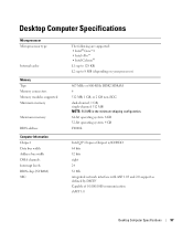
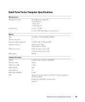
... Computer Specifications Microprocessor Microprocessor type Internal cache Memory Type Memory connectors Memory modules supported Minimum memory Maximum memory BIOS address Computer Information Chipset Data bus width Address bus width DMA channels Interrupt levels BIOS chip (NVRAM) NIC The following are supported: • Intel® Core™2 • Intel vPro™ • Intel...
... Computer Specifications Microprocessor Microprocessor type Internal cache Memory Type Memory connectors Memory modules supported Minimum memory Maximum memory BIOS address Computer Information Chipset Data bus width Address bus width DMA channels Interrupt levels BIOS chip (NVRAM) NIC The following are supported: • Intel® Core™2 • Intel vPro™ • Intel...
User's Guide
Page 38
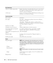
... to enter a device for a single boot (during start-up only) as well as options to run hard drive and system diagnostics displays the Management Engine BIOS Extension settings screen that power source. orange light for 100-Mb operation; solid green indicates power-on state. However, the computer draws a minute amount of...
... to enter a device for a single boot (during start-up only) as well as options to run hard drive and system diagnostics displays the Management Engine BIOS Extension settings screen that power source. orange light for 100-Mb operation; solid green indicates power-on state. However, the computer draws a minute amount of...
User's Guide
Page 94
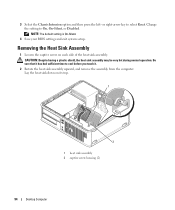
..., and remove the assembly from the computer. Change the setting to On, On-Silent, or Disabled. NOTE: The default setting is On-Silent. 4 Save your BIOS settings and exit system setup. CAUTION: Despite having a plastic shield, the heat sink assembly may be very hot during normal operation. 3 Select the Chassis Intrusion...
..., and remove the assembly from the computer. Change the setting to On, On-Silent, or Disabled. NOTE: The default setting is On-Silent. 4 Save your BIOS settings and exit system setup. CAUTION: Despite having a plastic shield, the heat sink assembly may be very hot during normal operation. 3 Select the Chassis Intrusion...
User's Guide
Page 97
... Computer Specifications Microprocessor Microprocessor type Internal cache Memory Type Memory connectors Memory modules supported Minimum memory Maximum memory BIOS address Computer Information Chipset Data bus width Address bus width DMA channels Interrupt levels BIOS chip (NVRAM) NIC The following are supported: • Intel® Core™2 • Intel vPro™ • Intel...
... Computer Specifications Microprocessor Microprocessor type Internal cache Memory Type Memory connectors Memory modules supported Minimum memory Maximum memory BIOS address Computer Information Chipset Data bus width Address bus width DMA channels Interrupt levels BIOS chip (NVRAM) NIC The following are supported: • Intel® Core™2 • Intel vPro™ • Intel...
User's Guide
Page 101
... computer starts embedded system setup (during system start-up only) as well as options to run hard drive and system diagnostics displays the Management Engine BIOS Extension settings screen that allows you to enter a device for a single boot (during system start -up only) displays a boot device menu that allows the user...
... computer starts embedded system setup (during system start-up only) as well as options to run hard drive and system diagnostics displays the Management Engine BIOS Extension settings screen that allows you to enter a device for a single boot (during system start -up only) displays a boot device menu that allows the user...
User's Guide
Page 172
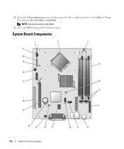
System Board Components 1 2 3 21 20 19 4 18 17 5 6 16 7 15 14 13 12 11 172 Small Form Factor Computer 10 9 8 NOTE: The default setting is On-Silent. 4 Save your BIOS settings and exit system setup. 3 Select the Chassis Intrusion option and then press the left- Change the setting to select Reset. or right-arrow key to On, On-Silent, or Disabled.
System Board Components 1 2 3 21 20 19 4 18 17 5 6 16 7 15 14 13 12 11 172 Small Form Factor Computer 10 9 8 NOTE: The default setting is On-Silent. 4 Save your BIOS settings and exit system setup. 3 Select the Chassis Intrusion option and then press the left- Change the setting to select Reset. or right-arrow key to On, On-Silent, or Disabled.
User's Guide
Page 175
... Computer Specifications Microprocessor Microprocessor type Internal cache Memory Type Memory connectors Memory modules supported Minimum memory Maximum memory BIOS address Computer Information Chipset Data bus width Address bus width DMA channels Interrupt levels BIOS chip (NVRAM) NIC The following are supported: • Intel® Core™2 • Intel vPro™ • Intel...
... Computer Specifications Microprocessor Microprocessor type Internal cache Memory Type Memory connectors Memory modules supported Minimum memory Maximum memory BIOS address Computer Information Chipset Data bus width Address bus width DMA channels Interrupt levels BIOS chip (NVRAM) NIC The following are supported: • Intel® Core™2 • Intel vPro™ • Intel...
User's Guide
Page 178
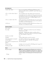
...1000-Mb (1-Gb) operation Activity light (on integrated network yellow blinking light adapter) Diagnostic lights four lights on the front panel (See "Dell Diagnostics" on page 353.) Standby power light AUX_PWR on the system board Power DC power supply: Wattage NOTE: Power consumption from an AC ...® Windows® XP, brings up only) as well as options to run hard drive and system diagnostics displays the Management Engine BIOS Extension settings screen that allows you to enter a device for 10-Mb operation; amber light - solid green indicates power-on integrated network...
...1000-Mb (1-Gb) operation Activity light (on integrated network yellow blinking light adapter) Diagnostic lights four lights on the front panel (See "Dell Diagnostics" on page 353.) Standby power light AUX_PWR on the system board Power DC power supply: Wattage NOTE: Power consumption from an AC ...® Windows® XP, brings up only) as well as options to run hard drive and system diagnostics displays the Management Engine BIOS Extension settings screen that allows you to enter a device for 10-Mb operation; amber light - solid green indicates power-on integrated network...
User's Guide
Page 235
...the setting to wait until you see the Microsoft® Windows® desktop. Resetting the Chassis Intrusion Detector 1 Turn on (or restart) your BIOS settings and exit system setup. If you wait too long and the operating system logo appears, continue to On, On-Silent, or Disabled. or ...right-arrow key to select Reset. NOTE: The default setting is On-Silent. 4 Save your computer. 2 When the blue DELL™ logo appears, press immediately. Ultra Small Form Factor Computer 235 Then shut down your computer and try again. 3 Select the Chassis Intrusion option and...
...the setting to wait until you see the Microsoft® Windows® desktop. Resetting the Chassis Intrusion Detector 1 Turn on (or restart) your BIOS settings and exit system setup. If you wait too long and the operating system logo appears, continue to On, On-Silent, or Disabled. or ...right-arrow key to select Reset. NOTE: The default setting is On-Silent. 4 Save your computer. 2 When the blue DELL™ logo appears, press immediately. Ultra Small Form Factor Computer 235 Then shut down your computer and try again. 3 Select the Chassis Intrusion option and...
User's Guide
Page 241
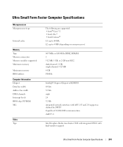
... Computer Specifications Microprocessor Microprocessor type Internal cache Memory Type Memory connectors Memory modules supported Minimum memory Maximum memory BIOS address Computer Information Chipset Data bus width Address bus width DMA channels Interrupt levels BIOS chip (NVRAM) NIC Video Type The following are supported: • Intel® Core™2 • Intel vPro™...
... Computer Specifications Microprocessor Microprocessor type Internal cache Memory Type Memory connectors Memory modules supported Minimum memory Maximum memory BIOS address Computer Information Chipset Data bus width Address bus width DMA channels Interrupt levels BIOS chip (NVRAM) NIC Video Type The following are supported: • Intel® Core™2 • Intel vPro™...
User's Guide
Page 243
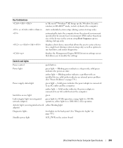
... devices in Microsoft® Windows® XP, brings up only) as well as options to run hard drive and system diagnostics displays the Management Engine BIOS Extension settings screen that allows you to an AC outlet and the computer. Solid green indicates the power adapter is connected to an AC outlet...
... devices in Microsoft® Windows® XP, brings up only) as well as options to run hard drive and system diagnostics displays the Management Engine BIOS Extension settings screen that allows you to an AC outlet and the computer. Solid green indicates the power adapter is connected to an AC outlet...
User's Guide
Page 271
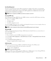
... for managing such a computer is enabled in an unusable state, or with the computer powered off. Accessing iAMT setup Intel's Management Engine BIOS Extension (MEBx) interface controls the iAMT features and setup options for AMT capability to Previous Menu twice. Your default MEBx password is being ...) firmware by default. NOTE: To make configuration setting changes, the default MEBx password must : • Be formatted using a USB key and Dell Client Manager. However, you turn it on or off iAMT • Set iAMT modes • Set iAMT configuration modes To view the MEBx setup...
... for managing such a computer is enabled in an unusable state, or with the computer powered off. Accessing iAMT setup Intel's Management Engine BIOS Extension (MEBx) interface controls the iAMT features and setup options for AMT capability to Previous Menu twice. Your default MEBx password is being ...) firmware by default. NOTE: To make configuration setting changes, the default MEBx password must : • Be formatted using a USB key and Dell Client Manager. However, you turn it on or off iAMT • Set iAMT modes • Set iAMT configuration modes To view the MEBx setup...
User's Guide
Page 273
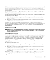
... Client Instrumentation User's Guide available on a console and its BIOS, configuring BIOS settings, or shutting it is a managed computer. With Dell Client Manager installed on the Dell Support website at support.dell.com. IT Assistant manages assets, configurations, events (alerts), and security for thermal alerts from temperature probes or hard drive failure alerts from storage...
... Client Instrumentation User's Guide available on a console and its BIOS, configuring BIOS settings, or shutting it is a managed computer. With Dell Client Manager installed on the Dell Support website at support.dell.com. IT Assistant manages assets, configurations, events (alerts), and security for thermal alerts from temperature probes or hard drive failure alerts from storage...

User's Guide
Page 281
.... This Option Field - scrollable list containing Press to make changes to highlight an option. System System Info Processor Info Memory Info Lists the computer name, BIOS Version, Service Tag, Express Service Code, (if applicable), and the Asset Tag. States whether the processor is a Use the right- For each field appears on...
.... This Option Field - scrollable list containing Press to make changes to highlight an option. System System Info Processor Info Memory Info Lists the computer name, BIOS Version, Service Tag, Express Service Code, (if applicable), and the Asset Tag. States whether the processor is a Use the right- For each field appears on...


