
User Manual
Page 1
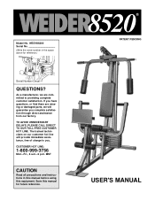
... on our customer hot line will guarantee you . CUSTOMER HOT LINE: 1-800-999-3756 Mon.-Fri., 6 a.m.-6 p.m. Model No. As a manufacturer, we are missing or damaged parts, we will provide immediate assistance, free of charge to providing complete customer satisfaction. If you have questions, or find there are committed to you complete...
... on our customer hot line will guarantee you . CUSTOMER HOT LINE: 1-800-999-3756 Mon.-Fri., 6 a.m.-6 p.m. Model No. As a manufacturer, we are missing or damaged parts, we will provide immediate assistance, free of charge to providing complete customer satisfaction. If you have questions, or find there are committed to you complete...
User Manual
Page 2
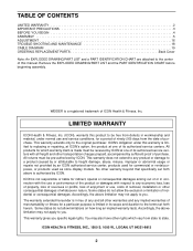
...PART IDENTIFICATION CHART before beginning assembly. No other warranty beyond that specifically set forth herein. ICON is not responsible or liable for a particular purpose is a registered trademark of this warranty is made must be pre-authorized by an ICON authorized service center, products used as store display models. WEIDER...4 ASSEMBLY 5 ADJUSTMENT 16 TROUBLE-SHOOTING AND MAINTENANCE 18 CABLE DIAGRAM 19 ORDERING REPLACEMENT PARTS Back Cover Note: An EXPLODED DRAWING/PART LIST and a PART IDENTIFICATION CHART are attached to the center of ICON Health & Fitness, Inc. All...
...PART IDENTIFICATION CHART before beginning assembly. No other warranty beyond that specifically set forth herein. ICON is not responsible or liable for a particular purpose is a registered trademark of this warranty is made must be pre-authorized by an ICON authorized service center, products used as store display models. WEIDER...4 ASSEMBLY 5 ADJUSTMENT 16 TROUBLE-SHOOTING AND MAINTENANCE 18 CABLE DIAGRAM 19 ORDERING REPLACEMENT PARTS Back Cover Note: An EXPLODED DRAWING/PART LIST and a PART IDENTIFICATION CHART are attached to the center of ICON Health & Fitness, Inc. All...

User Manual
Page 3
... of the owner to ensure that could cause the home gym system to be used by or through the use the lat bar. Read all parts often. Always wear athletic shoes for protection. 5. Make sure that does not use of serious injury, read the following important precautions before using . Keep small...
... of the owner to ensure that could cause the home gym system to be used by or through the use the lat bar. Read all parts often. Always wear athletic shoes for protection. 5. Make sure that does not use of serious injury, read the following important precautions before using . Keep small...
User Manual
Page 4
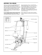
...number before Before reading further, please review the drawing using the WEIDER® 8520 Home Gym System. For your goal is WESY85200. BEFORE YOU BEGIN Thank you below and familiarize yourself with the parts that are have additional questions, please call our Customer labeled. ...If you for selecting the versatile WEIDER® 8520 Home Gym System. Length: 59 in . ASSEMBLED DIMENSIONS: Height: 76 in ....
...number before Before reading further, please review the drawing using the WEIDER® 8520 Home Gym System. For your goal is WESY85200. BEFORE YOU BEGIN Thank you below and familiarize yourself with the parts that are have additional questions, please call our Customer labeled. ...If you for selecting the versatile WEIDER® 8520 Home Gym System. Length: 59 in . ASSEMBLED DIMENSIONS: Height: 76 in ....
User Manual
Page 5
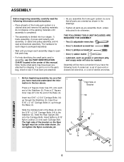
...51 14 1 4 1 27 5 FRAME ASSEMBLY 1. ASSEMBLY Before beginning assembly, carefully read and understand the information in the drawings. • Tighten all parts as grease or petroleum jelly, and soapy water will be needed. Press a 2" Square Inner Cap (27) into four stages: 1) frame assembly, ... pre-attached. • As you begin each assembly stage to do not dispose of the Stabilizer (5). Before beginning assembly, be sure that all parts are oriented as shown in the box above. Insert two 5/16" x 2 3/4" Carriage Bolts (14) up through the Stabilizer (5). Hand tighten...
...51 14 1 4 1 27 5 FRAME ASSEMBLY 1. ASSEMBLY Before beginning assembly, carefully read and understand the information in the drawings. • Tighten all parts as grease or petroleum jelly, and soapy water will be needed. Press a 2" Square Inner Cap (27) into four stages: 1) frame assembly, ... pre-attached. • As you begin each assembly stage to do not dispose of the Stabilizer (5). Before beginning assembly, be sure that all parts are oriented as shown in the box above. Insert two 5/16" x 2 3/4" Carriage Bolts (14) up through the Stabilizer (5). Hand tighten...
User Manual
Page 11
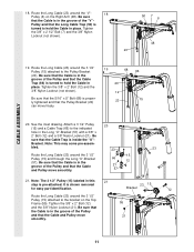
... (66) is in place. Attach a 3 1/2" Pulley 20 (15) and a Cable Trap (66) to the indicated hole in this 21 step is shown removed for easy part identification. 23 15 Bracket 12 Route the Long Cable (23) around the 3 1/2" Pulley (15) attached to hold the Cable in the groove of the Pulley...
... (66) is in place. Attach a 3 1/2" Pulley 20 (15) and a Cable Trap (66) to the indicated hole in this 21 step is shown removed for easy part identification. 23 15 Bracket 12 Route the Long Cable (23) around the 3 1/2" Pulley (15) attached to hold the Cable in the groove of the Pulley...
User Manual
Page 12
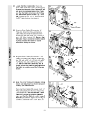
... Pulley (6). Be sure that the Cable Trap (66) is turned to the lower hole in place and that the Cable is shown removed for easy part identification. Attach the Pulley and a Long 23 Cable Trap (50) inside the bracket on the Leg Lever (29). It is routed around the Pulley as...
... Pulley (6). Be sure that the Cable Trap (66) is turned to the lower hole in place and that the Cable is shown removed for easy part identification. Attach the Pulley and a Long 23 Cable Trap (50) inside the bracket on the Leg Lever (29). It is routed around the Pulley as...
User Manual
Page 13
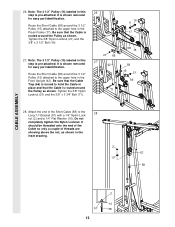
...). 26 21 66 27 42 9 71 16 9 17 58 15 58 15 21 66 28. It is shown removed for easy part identification. It is shown removed for easy part identification. Be sure that the Cable Trap (66) is turned to the upper hole in place and that the Cable is routed...
...). 26 21 66 27 42 9 71 16 9 17 58 15 58 15 21 66 28. It is shown removed for easy part identification. It is shown removed for easy part identification. Be sure that the Cable Trap (66) is turned to the upper hole in place and that the Cable is routed...

User Manual
Page 15
Be sure that all parts have been properly tightened. Insert the Short Pad Tube (28) into each end of the Long Pad ... a 3/4" Round Inner Cap into the Leg Lever (29). Remove the backing from the 8520 decal and apply it by tightening the cables. The use of the remaining parts will need to be explained in the cables, you will be sure that the cables move... a 5 1/2" Pad (30) onto each end of this way 33 34 30 28 36 30 34 80 30 34 29 8520 DECAL PLACEMENT 15 SEAT ASSEMBLY 32. See TROUBLE-SHOOTING AND MAINTENANCE on page 19 of the Short Pad Tube. Attach the Press Plate...
Be sure that all parts have been properly tightened. Insert the Short Pad Tube (28) into each end of the Long Pad ... a 3/4" Round Inner Cap into the Leg Lever (29). Remove the backing from the 8520 decal and apply it by tightening the cables. The use of the remaining parts will need to be explained in the cables, you will be sure that the cables move... a 5 1/2" Pad (30) onto each end of this way 33 34 30 28 36 30 34 80 30 34 29 8520 DECAL PLACEMENT 15 SEAT ASSEMBLY 32. See TROUBLE-SHOOTING AND MAINTENANCE on page 19 of the Short Pad Tube. Attach the Press Plate...
User Manual
Page 16
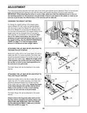
... Bar is performed, the effectiveness of the exercise will be performed. The Nylon Strap (39) can be adjusted. ADJUSTMENT The instructions below describe how each part of the home gym system can be attached in the same manner. Note: Due to the Long Cable (23) with two Cable Clips. For some...
... Bar is performed, the effectiveness of the exercise will be performed. The Nylon Strap (39) can be adjusted. ADJUSTMENT The instructions below describe how each part of the home gym system can be attached in the same manner. Note: Due to the Long Cable (23) with two Cable Clips. For some...
User Manual
Page 18
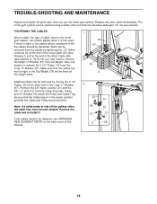
... slip off the pulleys often, the cable may have become twisted. Re-attach the Pulley and Cable Trap. Slack can be replaced, see ORDERING REPLACEMENT PARTS on the home gym system, can be removed by tightening the 1/4" Nylon Locknuts (2) at the end of the Long Cable (23) (see drawing ...1) and at the end of the Short Cable (58) (see drawing 2). TROUBLE-SHOOTING AND MAINTENANCE Inspect and tighten all parts each time you may need to be removed from the Cable Trap (66), Pulley, and "U"-Bracket. If there is slack in the Long "U"-Bracket 2 ...
... slip off the pulleys often, the cable may have become twisted. Re-attach the Pulley and Cable Trap. Slack can be replaced, see ORDERING REPLACEMENT PARTS on the home gym system, can be removed by tightening the 1/4" Nylon Locknuts (2) at the end of the Long Cable (23) (see drawing ...1) and at the end of the Short Cable (58) (see drawing 2). TROUBLE-SHOOTING AND MAINTENANCE Inspect and tighten all parts each time you may need to be removed from the Cable Trap (66), Pulley, and "U"-Bracket. If there is slack in the Long "U"-Bracket 2 ...

User Manual
Page 20
...: 1. Mountain Time (excluding holidays). The NAME of the product (WESY85200). 2. The MODEL NUMBER of the product (WEIDER® 8520 Home Gym System). 3. The KEY NUMBER and DESCRIPTION of the part(s) (see the front cover of this manual). The SERIAL NUMBER of the product (see the... PART LIST and EXPLODED DRAWING at 1-800-999-3756, Monday through Friday, 6 a.m. Part No. 132714 R0896A Printed in Canada © 1996 ICON ...
...: 1. Mountain Time (excluding holidays). The NAME of the product (WESY85200). 2. The MODEL NUMBER of the product (WEIDER® 8520 Home Gym System). 3. The KEY NUMBER and DESCRIPTION of the part(s) (see the front cover of this manual). The SERIAL NUMBER of the product (see the... PART LIST and EXPLODED DRAWING at 1-800-999-3756, Monday through Friday, 6 a.m. Part No. 132714 R0896A Printed in Canada © 1996 ICON ...
User Manual
Page 21
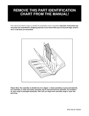
... divided into four stages: 1) frame assembly, 2) press and butterfly arm assembly, 3) cable and pulley assembly, and 4) seat and backrest assembly. if you identify the small parts used in the parts bags, check to see if it has been pre-assembled. WESY85200 R0896A The hardware for shipping purposes; Important: Some...
... divided into four stages: 1) frame assembly, 2) press and butterfly arm assembly, 3) cable and pulley assembly, and 4) seat and backrest assembly. if you identify the small parts used in the parts bags, check to see if it has been pre-assembled. WESY85200 R0896A The hardware for shipping purposes; Important: Some...
User Manual
Page 25
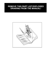
REMOVE THIS PART LIST/EXPLODED DRAWING FROM THE MANUAL! 81
REMOVE THIS PART LIST/EXPLODED DRAWING FROM THE MANUAL! 81
User Manual
Page 26
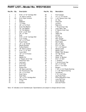
Specifications are subject to change without notice. PART LIST-Model No. Qty. 42 1 43 2 44 10 45 2 46 2 47 1 48 1 49 4 50 4 51 2 52 1 53 3 54 1 55 1 56 1 57 1 58... 1 1/8" x 2 1/2" Plastic Bushing 1" x 7/8" Plastic Bushing Top Weight 3 1/2" Low Pulley Leg Press Plate Press Adjustment Tube Long Pad Tube User's Manual Exercise Poster Note: "#" indicates a non-illustrated part. Qty. 1 4 2 3 3 20 4 1 5 1 6 4 7 5 8 8 9 5 10 6 11 6 12 3 13 1 14 2 15 8 16 3 17 1 18 2 19 2 20 1 21 16 22 5 23 1 24 1 25 8 26 1 27 ...
Specifications are subject to change without notice. PART LIST-Model No. Qty. 42 1 43 2 44 10 45 2 46 2 47 1 48 1 49 4 50 4 51 2 52 1 53 3 54 1 55 1 56 1 57 1 58... 1 1/8" x 2 1/2" Plastic Bushing 1" x 7/8" Plastic Bushing Top Weight 3 1/2" Low Pulley Leg Press Plate Press Adjustment Tube Long Pad Tube User's Manual Exercise Poster Note: "#" indicates a non-illustrated part. Qty. 1 4 2 3 3 20 4 1 5 1 6 4 7 5 8 8 9 5 10 6 11 6 12 3 13 1 14 2 15 8 16 3 17 1 18 2 19 2 20 1 21 16 22 5 23 1 24 1 25 8 26 1 27 ...


