Safety and Regulatory Information Desktops, Thin Clients, and Personal Workstations
Page 5
... Ergonomics Notice ...3 Laser Safety ...3 CDRH Regulations ...3 Compliance with International Regulations 4 Laser Product Label ...4 Laser Information ...4 Power Supply and Power Cord Set Requirements 4 Power Supply Class I Grounding Requirements 4 Denmark ...4 Norway ...4 Sweden ...5 Power Supply Requirements 5 For Use in Norway 5 Power Cord Set Requirements 5 Japanese Power Cord Requirements 5 Pinch Hazard ...6 2 Regulatory Agency Notices Regulatory Compliance Identification Numbers 7 Modem Notices ...7 Telecommunications Device Approvals...
... Ergonomics Notice ...3 Laser Safety ...3 CDRH Regulations ...3 Compliance with International Regulations 4 Laser Product Label ...4 Laser Information ...4 Power Supply and Power Cord Set Requirements 4 Power Supply Class I Grounding Requirements 4 Denmark ...4 Norway ...4 Sweden ...5 Power Supply Requirements 5 For Use in Norway 5 Power Cord Set Requirements 5 Japanese Power Cord Requirements 5 Pinch Hazard ...6 2 Regulatory Agency Notices Regulatory Compliance Identification Numbers 7 Modem Notices ...7 Telecommunications Device Approvals...
Safety and Regulatory Information Desktops, Thin Clients, and Personal Workstations
Page 7
... Safety Information 1 Always use in a grounded (earthed) outlet that is provided with your computer cover. Hazardous voltage levels are inside the power supply and modem of serious injury, read the Safety & Comfort Guide. 1 Safety Notices Important Safety Information WARNING! This guide is located on ... in the particular country/region where it . be easily accessible at www.hp.com/ergo and on the Web at all times. • Disconnect power from the thin client by unplugging the power cord from the telephone system before unplugging your equipment: • Do not...
... Safety Information 1 Always use in a grounded (earthed) outlet that is provided with your computer cover. Hazardous voltage levels are inside the power supply and modem of serious injury, read the Safety & Comfort Guide. 1 Safety Notices Important Safety Information WARNING! This guide is located on ... in the particular country/region where it . be easily accessible at www.hp.com/ergo and on the Web at all times. • Disconnect power from the thin client by unplugging the power cord from the telephone system before unplugging your equipment: • Do not...
Safety and Regulatory Information Desktops, Thin Clients, and Personal Workstations
Page 10
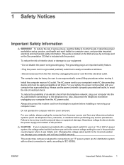
... or 10,869 W·m-2 sr-1 ● Polarization: Circular 0.25 ● Numerical Aperture: 0.45 +/- 0.04 Power Supply and Power Cord Set Requirements Power Supply Class I Grounding Requirements For protection from fault currents, the equipment shall be connected to the Class 1 Laser Product label... this product or a Hewlett-Packard authorized replacement. Plug the system power cord into an AC outlet that the product is located next to a grounding terminal. Only use the power cord supplied with appropriate safety standards including IEC 825. Compliance with International Regulations ...
... or 10,869 W·m-2 sr-1 ● Polarization: Circular 0.25 ● Numerical Aperture: 0.45 +/- 0.04 Power Supply and Power Cord Set Requirements Power Supply Class I Grounding Requirements For protection from fault currents, the equipment shall be connected to the Class 1 Laser Product label... this product or a Hewlett-Packard authorized replacement. Plug the system power cord into an AC outlet that the product is located next to a grounding terminal. Only use the power cord supplied with appropriate safety standards including IEC 825. Compliance with International Regulations ...
Safety and Regulatory Information Desktops, Thin Clients, and Personal Workstations
Page 11
... 100-127 or 200-240 volts AC. Particular attention should be found at http://www.hp.com/cgi-bin/hpsupport/index.pl. Use only the power cord provided with internal circuits that sense the incoming voltage and automatically switch to the plug... Power Supply Requirements The power supplies on or pinched by an acceptable accredited agency responsible for an IT power system with a damaged power cord set. ENWW Power Supply and Power Cord Set Requirements 5 For more information on those products that it . CAUTION: Do not use the product. Power supplies on power ...
... 100-127 or 200-240 volts AC. Particular attention should be found at http://www.hp.com/cgi-bin/hpsupport/index.pl. Use only the power cord provided with internal circuits that sense the incoming voltage and automatically switch to the plug... Power Supply Requirements The power supplies on or pinched by an acceptable accredited agency responsible for an IT power system with a damaged power cord set. ENWW Power Supply and Power Cord Set Requirements 5 For more information on those products that it . CAUTION: Do not use the product. Power supplies on power ...
Safety and Regulatory Information Desktops, Thin Clients, and Personal Workstations
Page 29
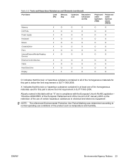
Table 2-2 Toxic and Hazardous Substances and Elements (continued) Part Name Lead (Pb) Mercury (Hg) Cadmium (Cd) Hexavalent Chromium (Cr(VI)) Memory X O O O I/O PCAs X O O O Power supply X O O O Keyboard X O O O Mouse X O O O Chassis/Other X O O O Fans X O O O Internal/External Media Reading X O O O Devices External Control Devices X O O O Cable X O O O Hard Disk Drive X O O O Display X X O O Polybrominated biphenyls (PBB) Polybrominated diphenyl ethers (PBDE) O O O O O O O O O O O O O O O O O O O O O O...
Table 2-2 Toxic and Hazardous Substances and Elements (continued) Part Name Lead (Pb) Mercury (Hg) Cadmium (Cd) Hexavalent Chromium (Cr(VI)) Memory X O O O I/O PCAs X O O O Power supply X O O O Keyboard X O O O Mouse X O O O Chassis/Other X O O O Fans X O O O Internal/External Media Reading X O O O Devices External Control Devices X O O O Cable X O O O Hard Disk Drive X O O O Display X X O O Polybrominated biphenyls (PBB) Polybrominated diphenyl ethers (PBDE) O O O O O O O O O O O O O O O O O O O O O O...

Quick Setup and Getting Started Guide
Page 17
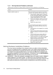
...: ▲ Select Start > HP Backup and Recovery > HP Backup and Recovery Manager Manual. To access HP Insight Diagnostics: ▲ Refer to " instructions for resolving possible hardware or software problems; includes information on RTC batteries, memory, and power supply. ● Computer Setup (F10...when installing new hardware devices. ● Desktop Management Guide-Provides definitions and "how to Accessing HP Insight Diagnostics in the Windows Regional Settings. To access HP user guides: ▲ Select Start > All Programs > HP User Manuals. If the Regional Settings do...
...: ▲ Select Start > HP Backup and Recovery > HP Backup and Recovery Manager Manual. To access HP Insight Diagnostics: ▲ Refer to " instructions for resolving possible hardware or software problems; includes information on RTC batteries, memory, and power supply. ● Computer Setup (F10...when installing new hardware devices. ● Desktop Management Guide-Provides definitions and "how to Accessing HP Insight Diagnostics in the Windows Regional Settings. To access HP user guides: ▲ Select Start > All Programs > HP User Manuals. If the Regional Settings do...

Quick Setup and Getting Started Guide
Page 24
... for less than 4 seconds. Check that appear on the screen. If it is set to the system board. To reduce the risk of the power supply on some models, is turned on . 3. Remove the expansion cards one at a time until the 5V_aux light on the system board turns on , then... the device and configures the computer. In Windows, use the Add Hardware Wizard and follow the instructions that the unit is off, then replace the power supply. 6. If the hard drive LED does not turn on your region. 2. Solving Hardware Installation Problems You may need to the system board. 4. Proper ...
... for less than 4 seconds. Check that appear on the screen. If it is set to the system board. To reduce the risk of the power supply on some models, is turned on . 3. Remove the expansion cards one at a time until the 5V_aux light on the system board turns on , then... the device and configures the computer. In Windows, use the Add Hardware Wizard and follow the instructions that the unit is off, then replace the power supply. 6. If the hard drive LED does not turn on your region. 2. Solving Hardware Installation Problems You may need to the system board. 4. Proper ...

Quick Setup and Getting Started Guide Enhanced for Accessibility
Page 17
... upgrading this computer and scenarios for maintenance purposes or when installing new hardware devices. ● Desktop Management Guide-Provides definitions and "how to Accessing HP Insight Diagnostics in English. Finding More Information The following publications are available on the computer hard...computers; Finding More Information 9 To access the HP Backup and Recovery Manager User Guide: ▲ Select Start > HP Backup and Recovery > HP Backup and Recovery Manager Manual. includes information on RTC batteries, memory, and power supply. ● Computer Setup (F10) Utility ...
... upgrading this computer and scenarios for maintenance purposes or when installing new hardware devices. ● Desktop Management Guide-Provides definitions and "how to Accessing HP Insight Diagnostics in English. Finding More Information The following publications are available on the computer hard...computers; Finding More Information 9 To access the HP Backup and Recovery Manager User Guide: ▲ Select Start > HP Backup and Recovery > HP Backup and Recovery Manager Manual. includes information on RTC batteries, memory, and power supply. ● Computer Setup (F10) Utility ...
Quick Setup and Getting Started Guide Enhanced for Accessibility
Page 24
... board. If you must reconfigure the computer after completing installation of the power supply on . To reduce the risk of the computer are properly connected to the appropriate voltage. Check that both power supply cables are not flashing. Check that the voltage selector, located on the... to the system board. 4. WARNING! Proper voltage setting depends on , then replace the power button harness. 5. When the computer is off, then replace the power supply. 6. OR Press and hold the power button for less than 4 seconds. If the 5V_aux light on the screen. In Windows...
... board. If you must reconfigure the computer after completing installation of the power supply on . To reduce the risk of the computer are properly connected to the appropriate voltage. Check that both power supply cables are not flashing. Check that the voltage selector, located on the... to the system board. 4. WARNING! Proper voltage setting depends on , then replace the power button harness. 5. When the computer is off, then replace the power supply. 6. OR Press and hold the power button for less than 4 seconds. If the 5V_aux light on the screen. In Windows...
Desktop Management Guide
Page 6
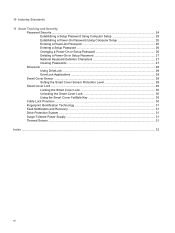
... Security Password Security ...24 Establishing a Setup Password Using Computer Setup 25 Establishing a Power-On Password Using Computer Setup 25 Entering a Power-On Password 25 Entering a Setup Password 26 Changing a Power-On or Setup Password 26 Deleting a Power-On or Setup Password 27 National Keyboard Delimiter Characters 27 Clearing Passwords ...27 DriveLock ... FailSafe Key 30 Cable Lock Provision ...30 Fingerprint Identification Technology 31 Fault Notification and Recovery ...31 Drive Protection System ...31 Surge-Tolerant Power Supply ...31 Thermal Sensor ...31 Index ...32 vi
... Security Password Security ...24 Establishing a Setup Password Using Computer Setup 25 Establishing a Power-On Password Using Computer Setup 25 Entering a Power-On Password 25 Entering a Setup Password 26 Changing a Power-On or Setup Password 26 Deleting a Power-On or Setup Password 27 National Keyboard Delimiter Characters 27 Clearing Passwords ...27 DriveLock ... FailSafe Key 30 Cable Lock Provision ...30 Fingerprint Identification Technology 31 Fault Notification and Recovery ...31 Drive Protection System ...31 Surge-Tolerant Power Supply ...31 Thermal Sensor ...31 Index ...32 vi
Desktop Management Guide
Page 36
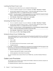
...you will need one of the following: ● Contact an authorized HP reseller or service provider. ● Call the appropriate number listed in... information about using the Smart Cover FailSafe Key, consult the Hardware Reference Guide. As soon as processor or power supply) ● Forgotten password CAUTION: The Smart Cover FailSafe Key is turned on , press F10 when the... the Smart Cover Lock To activate and lock the Smart Cover Lock, complete the following circumstances: ● Power outage ● Startup failure ● PC component failure (such as the computer is turned on , press...
...you will need one of the following: ● Contact an authorized HP reseller or service provider. ● Call the appropriate number listed in... information about using the Smart Cover FailSafe Key, consult the Hardware Reference Guide. As soon as processor or power supply) ● Forgotten password CAUTION: The Smart Cover FailSafe Key is turned on , press F10 when the... the Smart Cover Lock To activate and lock the Smart Cover Lock, complete the following circumstances: ● Power outage ● Startup failure ● PC component failure (such as the computer is turned on , press...
Desktop Management Guide
Page 37
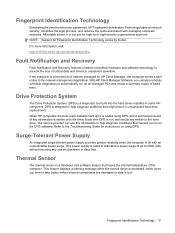
... 2000 volts without incurring any system downtime or data loss. Refer to enter user passwords, HP Fingerprint Identification Technology tightens network security, simplifies the login process, and reduces the costs associated with an unpredictable power surge. This power supply is a diagnostic tool built into the hard drives installed in unwarranted hard drive replacement. This...
... 2000 volts without incurring any system downtime or data loss. Refer to enter user passwords, HP Fingerprint Identification Technology tightens network security, simplifies the login process, and reduces the costs associated with an unpredictable power surge. This power supply is a diagnostic tool built into the hard drives installed in unwarranted hard drive replacement. This...
Desktop Management Guide
Page 39
... 2 asset tracking 23 Configuration Management Solution 8 Drive Protection System 31 HP Client Catalog for SMS 9 HP Client Management Interface 5 HP Client Manager for Altiris 8 HP ProtectTools Security Manager 7 HP System Software Manager 6 integration 2 recovery 2 Remote System Installation 4 updating and management tools 5 Subscriber's Choice 12 surge-tolerant power supply 31 System Software Manager 6 T temperature, internal computer 31 thermal...
... 2 asset tracking 23 Configuration Management Solution 8 Drive Protection System 31 HP Client Catalog for SMS 9 HP Client Management Interface 5 HP Client Manager for Altiris 8 HP ProtectTools Security Manager 7 HP System Software Manager 6 integration 2 recovery 2 Remote System Installation 4 updating and management tools 5 Subscriber's Choice 12 surge-tolerant power supply 31 System Software Manager 6 T temperature, internal computer 31 thermal...
Hardware Reference Guide - dc5800 Microtower Model
Page 29
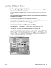
...chassis frame next to ensure the drive will line up correctly in the drive cage and lock in place. The HP-supplied metric guide screws (1) are silver and blue. The hard drive uses 6-32 isolation mounting guide screws. Figure ...2-15 Extra Guide Screws Location ENWW Installing Additional Drives 23 HP has provided extra guide screws installed on the system board in the following order: SATA0, SATA1, SATA5, SATA4. ●... half-height drive into a half-height bay. ● You must install guide screws to the power supply.
...chassis frame next to ensure the drive will line up correctly in the drive cage and lock in place. The HP-supplied metric guide screws (1) are silver and blue. The hard drive uses 6-32 isolation mounting guide screws. Figure ...2-15 Extra Guide Screws Location ENWW Installing Additional Drives 23 HP has provided extra guide screws installed on the system board in the following order: SATA0, SATA1, SATA5, SATA4. ●... half-height drive into a half-height bay. ● You must install guide screws to the power supply.
Hardware Reference Guide - dc5800 Microtower Model
Page 35
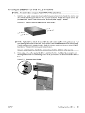
Install the four guide screws (two on each side) that were removed from the old drive to the new one. 2. The HP-supplied metric screws are provided on the interior of the chassis frame next to Installing Additional Drives on the interior of the chassis frame next to ... ATA (PATA) optical drives. 1. If you are provided on page 23 for an illustration of the bezel (1) and pull the bezel blank inwards to the power supply if needed. Extra guide screws are replacing a drive, transfer the guides screws from the old drive into its proper position in the bay. If necessary...
Install the four guide screws (two on each side) that were removed from the old drive to the new one. 2. The HP-supplied metric screws are provided on the interior of the chassis frame next to Installing Additional Drives on the interior of the chassis frame next to ... ATA (PATA) optical drives. 1. If you are provided on page 23 for an illustration of the bezel (1) and pull the bezel blank inwards to the power supply if needed. Extra guide screws are replacing a drive, transfer the guides screws from the old drive into its proper position in the bay. If necessary...
Hardware Reference Guide - dc5800 Microtower Model
Page 40
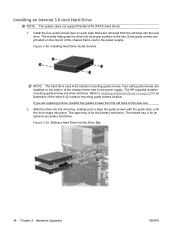
... mounting guide screws. Extra guide screws are installed on the interior of the chassis frame next to the power supply. Slide the drive into the drive bay, making sure to the new one. 2. Figure 2-29 Sliding...PATA) hard drives 1. The bottom bay is for an optional secondary hard drive. Refer to the power supply. Install the four guide screws (two on page 23 for an illustration of the chassis frame next ... until the drive snaps into the new drive. The HP-supplied isolation mounting guide screws are replacing a drive, transfer the guides screws from the old drive into ...
... mounting guide screws. Extra guide screws are installed on the interior of the chassis frame next to the power supply. Slide the drive into the drive bay, making sure to the new one. 2. Figure 2-29 Sliding...PATA) hard drives 1. The bottom bay is for an optional secondary hard drive. Refer to the power supply. Install the four guide screws (two on page 23 for an illustration of the chassis frame next ... until the drive snaps into the new drive. The HP-supplied isolation mounting guide screws are replacing a drive, transfer the guides screws from the old drive into ...
Hardware Reference Guide - dc5800 Microtower Model
Page 47
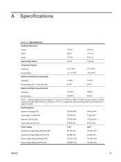
...-cal/hr Maximum (80 Plus PS) 1280 BTU/hr 323 kg-cal/hr Typical (idle; 80 Plus PS) 239 BTU/hr 60 kg-cal/hr Power Supply 115V 230V Operating Voltage Range (Standard PS)1 90-132 VAC 180-264 VAC Operating Voltage Range (80 Plus PS) 90-264 VAC 90-264 VAC... (Standard PS) 100-127 VAC 200-240 VAC Rated Voltage Range (80 Plus PS) 100-240 VAC 100-240 VAC ENWW 41 A Specifications Table A-1 Specifications Desktop Dimensions Height 19.94 in 50.65 cm Width 6.98 in 17.73 cm Depth 16.88 in 42.87 cm Approximate Weight 23.5 lb...
...-cal/hr Maximum (80 Plus PS) 1280 BTU/hr 323 kg-cal/hr Typical (idle; 80 Plus PS) 239 BTU/hr 60 kg-cal/hr Power Supply 115V 230V Operating Voltage Range (Standard PS)1 90-132 VAC 180-264 VAC Operating Voltage Range (80 Plus PS) 90-264 VAC 90-264 VAC... (Standard PS) 100-127 VAC 200-240 VAC Rated Voltage Range (80 Plus PS) 100-240 VAC 100-240 VAC ENWW 41 A Specifications Table A-1 Specifications Desktop Dimensions Height 19.94 in 50.65 cm Width 6.98 in 17.73 cm Depth 16.88 in 42.87 cm Approximate Weight 23.5 lb...

Hardware Reference Guide - dc5800 Microtower Model
Page 48
...CE mark requirements for use in the 230V operating mode only. The 80 Plus power supply utilizes an active power factor corrected power supply. Table A-1 Specifications (continued) Rated Line Frequency 50-60 Hz 50-60 Hz Power Output 300 W 300 W Rated Input Current (maximum)1 Standard PS 8A @ ...100 VAC 4A @ 200 VAC 80 Plus PS 4A @ 100VAC 2A @ 200VAC 1 The standard power supply utilizes a passive power factor corrected power supply. This supply requires the use in the countries of the European Union. This allows the system to pass the CE mark requirements for ...
...CE mark requirements for use in the 230V operating mode only. The 80 Plus power supply utilizes an active power factor corrected power supply. Table A-1 Specifications (continued) Rated Line Frequency 50-60 Hz 50-60 Hz Power Output 300 W 300 W Rated Input Current (maximum)1 Standard PS 8A @ ...100 VAC 4A @ 200 VAC 80 Plus PS 4A @ 100VAC 2A @ 200VAC 1 The standard power supply utilizes a passive power factor corrected power supply. This supply requires the use in the countries of the European Union. This allows the system to pass the CE mark requirements for ...
Hardware Reference Guide - dc5800 Microtower Model
Page 61
... ENWW HP Business PC Security Lock 48 padlock 48 M media card reader features 3 installing 29 removing 26 memory installing 14 populating sockets 15 specifications 14 microphone connector 2 monitor connector 4 mouse connector 4 N network connector 4 O optical drive cleaning 54 installing 29 precautions 54 removing 26 P PCI card 18, 20 PCI Express card 18, 20 power supply...
... ENWW HP Business PC Security Lock 48 padlock 48 M media card reader features 3 installing 29 removing 26 memory installing 14 populating sockets 15 specifications 14 microphone connector 2 monitor connector 4 mouse connector 4 N network connector 4 O optical drive cleaning 54 installing 29 precautions 54 removing 26 P PCI card 18, 20 PCI Express card 18, 20 power supply...
Illustrated Parts & Service Map: HP Compaq dc5800 Microtower Business PC
Page 1
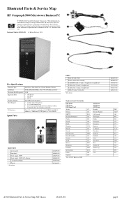
Illustrated Parts & Service Map HP Compaq dc5800 Microtower Business PC © 2008 Hewlett-Packard Development Company, L.P. and other countries. S. Chinese Slovakian Spanish Swedish Swiss Taiwanese Thai Turkish "F" Turkish "Q" U.S. Key Specifications...of the Intel Corporation and its subsidiaries in (2), audio out (2), PS/2 ports (2), VGA, DVI-D Spare Parts System Unit 1 Access panel 2 Front bezel 3 Power supply, 300W 3 Power supply, 300W, 80% efficient * 5.25-inch bezel blank * Chassis * Not shown 461859-001 460883-001 460879-001 460880-001 335937-001 not spared Cables 1 ...
Illustrated Parts & Service Map HP Compaq dc5800 Microtower Business PC © 2008 Hewlett-Packard Development Company, L.P. and other countries. S. Chinese Slovakian Spanish Swedish Swiss Taiwanese Thai Turkish "F" Turkish "Q" U.S. Key Specifications...of the Intel Corporation and its subsidiaries in (2), audio out (2), PS/2 ports (2), VGA, DVI-D Spare Parts System Unit 1 Access panel 2 Front bezel 3 Power supply, 300W 3 Power supply, 300W, 80% efficient * 5.25-inch bezel blank * Chassis * Not shown 461859-001 460883-001 460879-001 460880-001 335937-001 not spared Cables 1 ...


