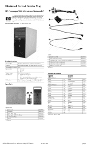
Dc5800 Illustrated - HP Compaq Business Desktop
Dc5800 Illustrated
Related Manual Pages


Similar Questions

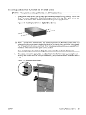
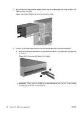
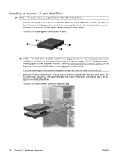
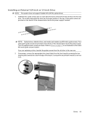
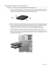
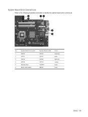
Illustrated Instructions
I haveHP pavilion model # a700n, system # pj516aa, product # hp pavilion mx704. When Ipurchased this...
I haveHP pavilion model # a700n, system # pj516aa, product # hp pavilion mx704. When Ipurchased this...
(Posted by tmworth01 11 years ago)
Related Terms
The following terms were also used when searching for Dc5800 Illustrated - HP Compaq Business Desktop:- hp dc5800 microtower
- hp dc5800 sff
- dc5800 sff
- hp dc5800s
- ka435ut aba
- ka435ut#aba
- dc5800 small form factor
- hp dc5800 small form factor
- dc5800 memory
- hp dc5800 bios
- dc5800 bios
- hp dc5800 memory
- nv308ut aba
- nv308ut#aba
- dc5800 microtower
- hp dc5800 drivers
- nv312ut aba
- nv312ut#aba
- nv315ut aba
- nv315ut#aba
- dc5800 drivers
- kr555ut aba
- kr555ut#aba
- ka491ua aba
- ka491ua#aba
- kr750ut aba
- kr781ut aba
- kr781ut#aba
- ka426ut aba
- ka426ut#aba
- dc5800s drivers
- kr591ut aba
- ak819aw aba
- hp ka426ut aba
- hp ka435ut aba
- kr551ut aba
- kr749ut aba
- dc5800 review
- hp dc5800s drivers
- ka405ut aba
- ka405ut#aba
- kr566ut aba
- kr566ut#aba
- kr779ut aba
- kr779ut#aba
- dc5800s specs
- hp dc5800 power supply
- hp dc5800 specs
- hp nv308ut aba
- ka406ut aba
- ka406ut#aba
- ka503ua aba
- kr558ut aba
- kr559ut aba
- nv303ut aba
- nv310ut aba
- dc5800 beep codes
- dc5800 power supply
- dc5800 red light
- dc5800 specs
- dc5800 unknown device
- dc5800s desktop
- hp dc5800s desktop
- nv314ut aba
- nv314ut#aba
- ak819aw aba hp
- ak819aw aba number
- ak819aw aba specs
- ak819aw manual
- ak819aw price
- ak819aw specs
- ak819aw#aba
- at511aw aba
- at511aw aba number
- at511aw#aba
- at819us aba number
- au313us aba
- au313us aba number
- au313us#aba
- au487us aba number
- av774us aba number
- aw458us aba number
- aw459us aba number
- dc5800
- dc5800 3 beeps
- dc5800 4gb ram upgrade
- dc5800 5 beeps
- dc5800 ahci
- dc5800 audio
- dc5800 audio driver
- dc5800 audio driver windows 7
- dc5800 audio driver xp
- dc5800 audio drivers
- dc5800 bios download
- dc5800 bios password reset
- dc5800 bios update
- dc5800 bios update windows
- dc5800 chipset driver
- dc5800 clear
- dc5800 computer
- dc5800 core 2 duo 2.33 ghz
- dc5800 cpu upgrade
- dc5800 desktop
- dc5800 desktop computer
- dc5800 desktop pc
- dc5800 desktop pc specs
- dc5800 desktop specs
- dc5800 diagram
- dc5800 downloads
- dc5800 driver
- dc5800 drivers download
- dc5800 drivers for windows 7
- dc5800 drivers hp
- dc5800 drivers windows 7
- dc5800 drivers xp
- dc5800 dual monitor
- dc5800 dual video card
- dc5800 expansion slots
- dc5800 graphics
- dc5800 graphics card
- dc5800 heci
- dc5800 heci driver
- dc5800 hp
- dc5800 hp computer
- dc5800 hp desktop
- dc5800 hp sound realtek driver
- dc5800 hp specs
- dc5800 hp windows 7 sound realtek driver
- dc5800 illustrated
- dc5800 manual
- dc5800 max memory
- dc5800 max ram
- dc5800 memory specs
- dc5800 memory upgrade
- dc5800 microtower drivers
- dc5800 microtower motherboard
- dc5800 microtower specs
- dc5800 motherboard
- dc5800 motherboard layout
- dc5800 motherboard specs
- dc5800 mt
- dc5800 mt drivers
- dc5800 network driver
- dc5800 overclock
- dc5800 pci controller driver
- dc5800 pci driver
- dc5800 pci simple communication
- dc5800 pci simple communication controller
- dc5800 pci simple communication driver
- dc5800 pci simple communications
- dc5800 pci simple communications controller
- dc5800 pci simple communications driver
- dc5800 place graphic card
- dc5800 processor upgrade
- dc5800 product numbers
- dc5800 quad
- dc5800 ram
- dc5800 recovery disk
- dc5800 refurbished
- dc5800 release date
- dc5800 replace
- dc5800 replacement fan
- dc5800 replacement parts
- dc5800 replacement video card
- dc5800 restore disks
- dc5800 reviews
- dc5800 sata drivers
- dc5800 sff desktop
- dc5800 sff driver
- dc5800 sff drivers
- dc5800 sff forums
- dc5800 sff motherboard
- dc5800 sff power supply
- dc5800 sff specifications
- dc5800 simple communications controller
- dc5800 simple communications driver
- dc5800 slimline pci express video card
- dc5800 small form
- dc5800 small form factor drivers
- dc5800 small form factor specs
- dc5800 sound driver
- dc5800 sound driver windows 7
- dc5800 sound drivers
- dc5800 sound drivers for windows 7
- dc5800 specification
- dc5800 specifications
- dc5800 specs small form factor
- dc5800 ssd
- dc5800 support
- dc5800 unknown device driver
- dc5800 unknown devices
- dc5800 usb boot
- dc5800 video card
- dc5800 video card upgrade
- dc5800 video controller driver
- dc5800 vpro
- dc5800 windows 10
- dc5800 windows 7
- dc5800 windows 7 drivers
- dc5800 windows 7 pci simple
- dc5800 windows 7 sound driver
- dc5800 windows 8 drivers
- dc5800 wol
- dc5800 xp drivers
- dc5800s video card
- fm696up aba number
- hp compaq dc5800 small form factor
- hp dc5800
- hp dc5800 4gb ram upgrade
- hp dc5800 5 beeps
- hp dc5800 ahci
- hp dc5800 audio
- hp dc5800 audio driver
- hp dc5800 audio drivers
- hp dc5800 beep codes
- hp dc5800 bios download
- hp dc5800 bios password reset
- hp dc5800 bios update
- hp dc5800 bios update windows
- hp dc5800 computer
- hp dc5800 core 2 duo 2.33 ghz
- hp dc5800 cpu upgrade
- hp dc5800 desktop
- hp dc5800 desktop computer
- hp dc5800 desktop pc
- hp dc5800 desktop specs
- hp dc5800 diagram
- hp dc5800 driver
- hp dc5800 drivers download
- hp dc5800 drivers for windows 7
- hp dc5800 drivers windows 7
- hp dc5800 drivers xp
- hp dc5800 dual monitor
- hp dc5800 dual video card
- hp dc5800 graphics card
- hp dc5800 heci driver
- hp dc5800 manual
- hp dc5800 max ram
- hp dc5800 memory specs
- hp dc5800 memory upgrade
- hp dc5800 microtower drivers
- hp dc5800 microtower motherboard
- hp dc5800 microtower specs
- hp dc5800 motherboard
- hp dc5800 motherboard layout
- hp dc5800 motherboard specs
- hp dc5800 mt
- hp dc5800 network driver
- hp dc5800 pci controller driver
- hp dc5800 pci driver
- hp dc5800 pci simple communication controller
- hp dc5800 pci simple communications
- hp dc5800 pci simple communications driver
- hp dc5800 place graphic card
- hp dc5800 processor upgrade
- hp dc5800 product numbers
- hp dc5800 ram
- hp dc5800 red light
- hp dc5800 refurbished
- hp dc5800 release date
- hp dc5800 replace
- hp dc5800 replacement parts
- hp dc5800 replacement video card
- hp dc5800 restore disks
- hp dc5800 review
- hp dc5800 reviews
- hp dc5800 sff desktop
- hp dc5800 sff drivers
- hp dc5800 sff specifications
- hp dc5800 simple communications controller
- hp dc5800 slimline pci express video card
- hp dc5800 small form factor drivers
- hp dc5800 small form factor specs
- hp dc5800 sound driver
- hp dc5800 sound driver windows 7
- hp dc5800 sound drivers
- hp dc5800 specification
- hp dc5800 specifications
- hp dc5800 specs small form factor
- hp dc5800 support
- hp dc5800 unknown device
- hp dc5800 unknown device driver
- hp dc5800 video card
- hp dc5800 video controller driver
- hp dc5800 windows 10
- hp dc5800 windows 7 drivers
- hp dc5800 windows 7 sound driver
- hp dc5800 xp drivers
- hp dc5800s specs
- hp dc5800s video card
- hp ka406ut aba
- hp ka426ut#aba
- hp ka435ut aba specs
- hp ka435ut#aba
- hp ka503ua aba
- hp ka503ua#aba
- hp kr591ut aba
- hp kr750ut aba
- hp kr779ut#aba
- hp nv303ut#aba
- hp nv312ut aba
- hp nv315ut aba
- hp nv315ut#aba
- ka405ut aba number
- ka405ut aba specs
- ka405ut specs
- ka406ut aba number
- ka406ut specs
- ka423ut aba number
- ka426ut aba hp
- ka426ut aba number
- ka426ut aba specs
- ka426ut specs
- ka435ut aba hp
- ka435ut aba memory
- ka435ut aba number
- ka435ut aba specs
- ka435ut drivers
- ka435ut memory
- ka435ut smart 2 0
- ka435ut specifications
- ka435ut specs
- ka435ut warranty
- ka435ut# aba
- ka435ut#aba specs
- ka488ua aba
- ka488ua aba number
- ka488ua#aba
- ka490ua aba
- ka490ua aba number
- ka490ua#aba
- ka491ua aba hp
- ka491ua aba number
- ka491ua aba specs
- ka491ua memory configuration
- ka491ua price
- ka491ua specs
- ka503ua aba number
- ka503ua aba specs
- ka503ua specs
- ka503ua#aba
- ka505ua aba
- ka505ua aba number
- ka505ua aba specs
- kr551ut aba number
- kr551ut aba specs
- kr551ut specs
- kr551ut#aba
- kr555ut aba number
- kr555ut aba specs
- kr555ut specs
- kr558ut aba number
- kr558ut aba specs
- kr558ut specs
- kr558ut#aba
- kr559ut aba memory
- kr559ut aba number
- kr559ut aba specs
- kr559ut specs
- kr559ut#aba
- kr563ut aba
- kr563ut aba number
- kr563ut specifications
- kr563ut specs
- kr563ut#aba
- kr566ut aba number
- kr566ut aba specs
- kr566ut specs
- kr591ut aba hp
- kr591ut aba number
- kr591ut aba specs
- kr591ut#aba
- kr749ut aba number
- kr749ut aba specs
- kr749ut specs
- kr749ut#aba
- kr750ut aba hp
- kr750ut aba number
- kr750ut aba specs
- kr750ut specs
- kr750ut#aba
- kr751ut aba
- kr751ut aba number
- kr754ut aba
- kr754ut aba number
- kr771ua aba
- kr771ua aba number
- kr771ua#aba
- kr773ua aba number
- kr779ut aba number
- kr779ut aba specs
- kr779ut price
- kr779ut specs
- kr779ut#abl
- kr781ut aba hp
- kr781ut aba number
- kr781ut aba specs
- kr781ut specs
- kr781ut warranty
- nv303ut aba hp
- nv303ut aba number
- nv303ut aba specs
- nv303ut specs
- nv303ut warranty
- nv303ut#aba
- nv307ut aba
- nv307ut aba number
- nv307ut#aba
- nv308ut aba number
- nv308ut aba specifications
- nv308ut aba specs
- nv308ut drivers
- nv308ut memory
- nv308ut quick specs
- nv308ut ram
- nv308ut specifications
- nv308ut specs
- nv308ut-smart
- nv310ut aba number
- nv310ut aba specs
- nv310ut prices
- nv310ut review
- nv310ut specs
- nv310ut#aba
- nv312ut #aba
- nv312ut aba number
- nv312ut aba specs
- nv312ut driver
- nv312ut memory
- nv312ut specs
- nv312ut warranty
- nv312ut weight
- nv312ut#aba specs
- nv314ut aba number
- nv314ut aba specs
- nv314ut specs
- nv315ut aba number
- nv315ut aba specs
- nv315ut price
- nv315ut review
- nv315ut specifications
- nv315ut specs
- nv315ut warranty
- nv315ut#aba specs
- nv315ut-smart
- nv324ua aba
- nv324ua aba number